YSP_Users_E.pdf - 第31页
xxviii Safety instructions 3.4 Label positions T he following warning/caution labels are attached to the Y AMAHA products to ensure safe and correct use. Check that the information on eac h label is clearly legible and c…
xxvii
Safety instructions
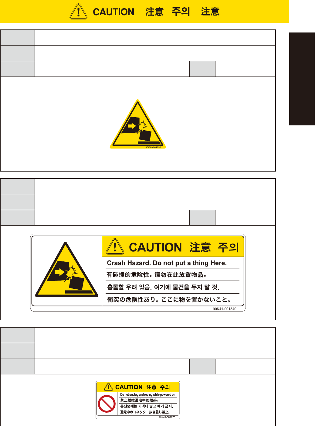
Potential
hazard
Could cause machine damage (collisions with head, etc.).
To avoid
hazard
Verify that no objects have been placed on the top cover of the feeder exchange carriage (for
YSM40 and Z:LEX (YSM20
))
.
Applicable
machines
Feeder exchange carriage
(YSM40/YSM40R, Z:LEX(YSM20/YSM20W))
Case
Setup
Potential
hazard
Could cause machine damage (collisions with head, etc.).
To avoid
hazard
Verify that no objects have been placed on the top cover of the feeder exchange carriage (for YSM40
and Z:LEX (YSM20)).
Applicable
machines
Feeder exchange carriage
(YSM40/YSM40R, Z:LEX(YSM20/YSM20W))
Case
Setup
Potential
hazard
Machine damage
To avoid
hazard
Do not insert or remove any connector while power is on.
Applicable
machines
cATS10 (Z:LEX(YSM20/YSM20W) )
Case
Setup
xxviii
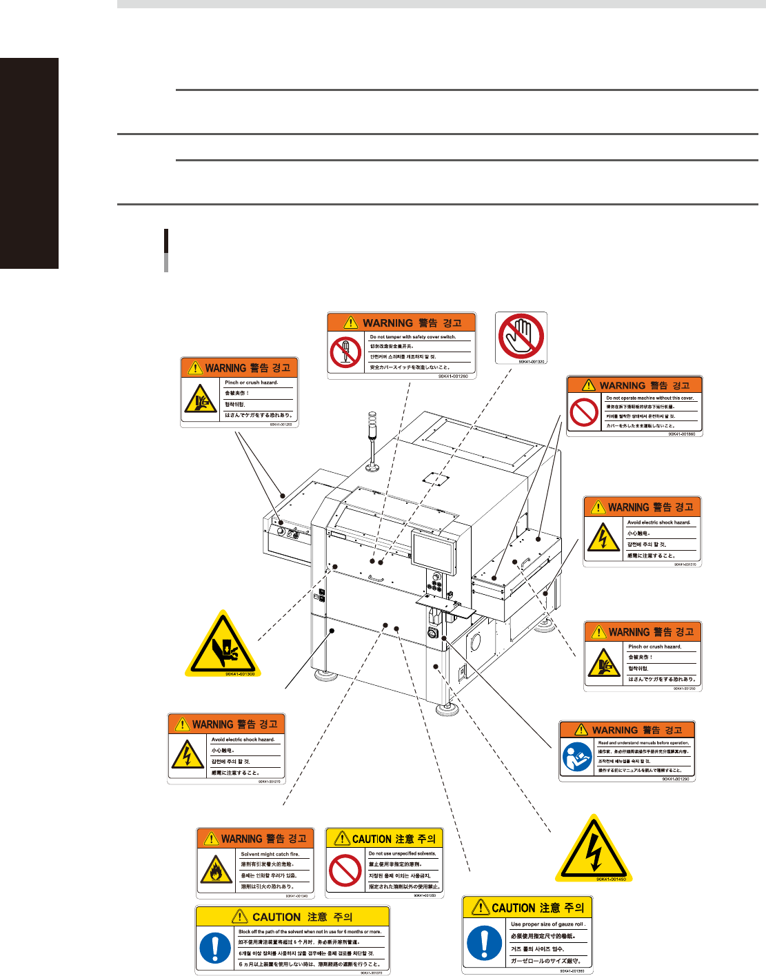
Safety instructions
3.4 Label positions
The following warning/caution labels are attached to the YAMAHA products to ensure safe and correct use.
Check that the information on each label is clearly legible and comply with the instructions.
For safety precautions other than those on the labels shown in this section, see the instructions in "1. Safety".
n
NOTE
Basically, labels are attached to the positions shown below, although they may differ slightly depending on the
machine model.
n
NOTE
When connecting power to this equipment, refer to "Power connection terminals" described in the appendix of the
maintenance manual or user's manual.
Warning/caution labels
YSP
■ Open/close cover inner side
■ Cover cover
■ Cover cover inner side
■ Main switch
■ Conveyor opening
(left and right) ,
Conveyor extension
on exit side (left and right)
■ Printing table/mask clamp
(inside safety cover)
■ Left side and Right side
■ Cleaning alcohol (behind front cover)
■ Behind front cover
■ Lower panels (front and rear)
■ Panel inner side
■ Vision camera unit
93201-L3-30

General Contents
About this manual
1. About this manual i
1.1 Revision record i
1.2 Contents of each chapter ii
1.3 Page layout iii
Chapter 1 Part names and functions
1. YSP main unit 1-1
2. Operation panels and data input units 1-4
2.1 Operation panel buttons 1-5
2.2 Keyboard and mouse 1-6
2.3 Liquid crystal touch screen (option) 1-6
3. Printing section 1-7
3.1 Squeegee head and printing table 1-7
3.2 3S squeegee 1-8
3.3 Double squeegee (option) 1-9
4. Conveyor unit 1-10
4.1 Board clamp unit (board clamp table) 1-10
4.2 Board support 1-11
4.3 Board carry-in and carry-out conveyors 1-15
4.4 Extended exit conveyor (option) 1-15
4.4.1 MANUAL mode 1-16
4.4.2 AUTO mode 1-17
5. Cleaning unit 1-18
5.1 Cleaning unit 1-18
5.2 Suction unit 1-19
6. Camera unit 1-20
7. Servo-controlled axes 1-21
Chapter 2 Basic operations
1. Canceling emergency stop and clearing an error 2-1
1.1 Canceling emergency stop 2-1
1.2 Clearing an error 2-2
1.3 Typical errors and troubleshooting 2-3
EUL3181200