YSP_Users_E.pdf - 第252页
A-1 A Appendix 1. Specifications 1.1 Air regulator unit 1.1.1 Air supply T he air pressure regulator is located behind the front lower left panel of the machine. The air pressure regulator must be correctly set to supply…

Appendix
Contents
1. Specifications A-1
1.1 Air regulator unit A-1
1.1.1 Air supply A-1
1.2 Connection between machines A-2
1.2.1 PREVIOUS INTERFACE connector A-3
1.2.2 NEXT INTERFACE connector A-4
1.3 Power connection terminals A-5
2. Compatible masks A-6
2.1 Mask size and mask stopper pin position A-6
2.2 Mask frame dimensions and mask standard position A-7
3. Inverter (suction unit) A-8
4. Board support jig combinations A-9
A-1
A
Appendix
1. Specifications
1.1 Air regulator unit
1.1.1 Air supply
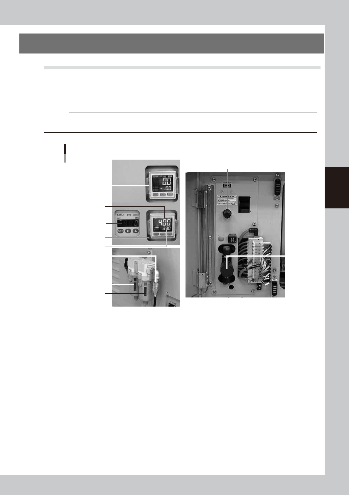
The air pressure regulator is located behind the front lower left panel of the machine. The air pressure regulator
must be correctly set to supply the machine at an optimum air pressure.
c
CAUTION
Before setting the air pressure, make sure that the pressure from the primary air supply is within an appropriate range
(0.45MPa or less).
Air pressure regulator and air connector
Air filter
Mist filter
3
Pressure-drop
detection level
Set air pressure level
2
1
4
5
6
63004-L3-00
1. Air pressure display
Shows the set air pressure level (upper portion) and the pressure-drop detection level (lower portion). Use the pressure
regulator knob to display the pressure levels described below.
Note that the pressure-drop detection level has been set at the value shown below before shipment from the factory.
• Set air pressure level: 0.40MPa
• Pressure-drop detection level: 0.33MPa
2. Supply air pressure regulator valve knob
Use this knob to adjust the supply air pressure to a proper set pressure level.
Turn the knob to adjust the supply air pressure so that the set air pressure level shows “0.40MPa”.
3. Air pressure supply/shutoff switch
Turning this switch to the right shuts off air supply and exhausts air that remains inside the machine.
4. Pressure gauge (for edge clamp)
Shows the edge clamp air pressure.
5. Pressure gauge (for cleaner suction)
Shows the cleaner's vacuum air pressure level (negative pressure level).
6. Source air connector
Prepare an air hose with an inner diameter of at least 8mm having a 30SH socket (Nitto Koki, or equivalent), and connect
it to this connector. Use dry, clean air passed through an air filter.
A-2
A
Appendix
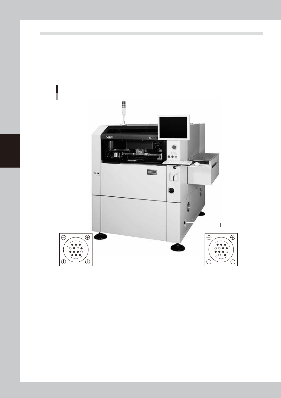
1.2 Connection between machines
To exchange signals such as board request and operation status with the downstream or upstream machine, the
"NEXT INTERFACE" and "PREVIOUS INTERFACE" connectors located on both sides of the machine are used.
The "NEXT INTERFACE" connector connects to the downstream machine, and the "PREVIOUS INTERFACE"
connector connects to the upstream machine such as a loader. In the case of standard right-to-left flow, the
PREVIOUS INTERFACE connector is located on the right side panel and the NEXT INTERFACE connector on the
left side panel when viewed from the front of the machine. Both connectors use a 14-pin receptacle (AMP
206043-1).
PREVIOUS INTERFACE NEXT INTERFACE
Machine-to-machine interface connectors
Connector : AMP 206043-1 (14-pin receptacle)
14
11
12
7
4
8
3
1
14
11
12
7
4
8
1
3
63005-L3-00