YSP_Users_E.pdf - 第42页
Chapter 1 Par t names and functions T his chapter explains YSP major part names and functions. Make sure that you understand the location and function of eac h part before attempting machine operation. Contents 1. YSP ma…
iii
About this manual
1.3 Page layout
The description below shows a typical page layout used in this manual.
3-5
3
Daily operation
4. Changing the conveyor unit setup
When producing boards that are different from the previous production board, you need to change the
conveyor unit setup to match the selected board. (This procedure is not necessary when you are producing
the same board as last time.)
c
CAUTION
When producing board whose width is narrower than the previous production board, remove in advance the push-up
jigs (or backup pins) from the push-up plate.
1
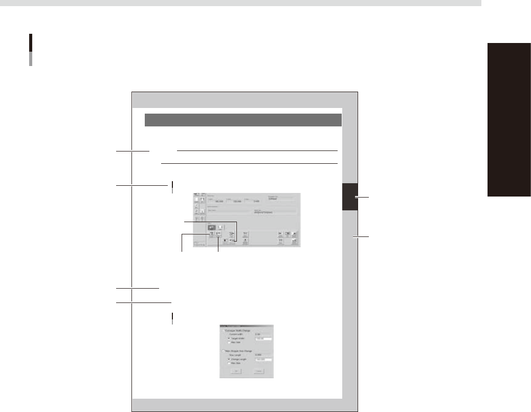
Open the [Unit]-[Conveyor] tab.
The buttons on this screen are used in the following steps to change the conveyor unit setup.
[Unit]-[Conveyor] tab
Step 3:
[Conv-MS Axis Position] button
Step 2:
[SW. Prod. Position] button
Step 6:
[Convey In]
button
64306-L3-00
2
Press the [SW. Prod. Position] button.
The conveyor table rises to the same height as the conveyor rails and the squeegee head moves to the
escape position (inner side).
3
Adjust the conveyor width and main stopper position.
1. Press the [Conv-MS Axis Position] button.
The dialog box appears for changing the conveyor width and main stopper position.
2. Check the board width and length shown in the dialog box and press the [OK] button.
The conveyor width and main stopper position are automatically changed to match the board size.
Dialog box for changing conveyor width and main stopper position
64307-L3-00
Typical page layout
Step
Chapter number
Chapter title
Sub step or
description of step
Figure, picture
or table caption
Note, Caution
or Warning
63003-L3-00
n
Step
This describes the procedure for each operation.
n
Substep or description of step
This provides detailed information on the steps in each procedure.
n
Illustration or table caption
This is the title of the illustration or table and appears at the upper left.
n
Note, Caution or Warning
These are explained in detail in "Safety instructions".

Chapter 1 Part names and functions
This chapter explains YSP major part names and functions. Make sure that you understand the location and function of each
part before attempting machine operation.
Contents
1. YSP main unit 1-1
2. Operation panels and data input units 1-4
2.1 Operation panel buttons 1-5
2.2 Keyboard and mouse 1-6
2.3 Liquid crystal touch screen (option) 1-6
3. Printing section 1-7
3.1 Squeegee head and printing table 1-7
3.2 3S squeegee 1-8
3.3 Double squeegee (option) 1-9
4. Conveyor unit 1-10
4.1 Board clamp unit (board clamp table) 1-10
4.2 Board support 1-11
4.3 Board carry-in and carry-out conveyors 1-15
4.4 Extended exit conveyor (option) 1-15
4.4.1 MANUAL mode 1-16
4.4.2 AUTO mode 1-17
5. Cleaning unit 1-18
5.1 Cleaning unit 1-18
5.2 Suction unit 1-19
6. Camera unit 1-20
7. Servo-controlled axes 1-21
1-1
1
Part names and functions
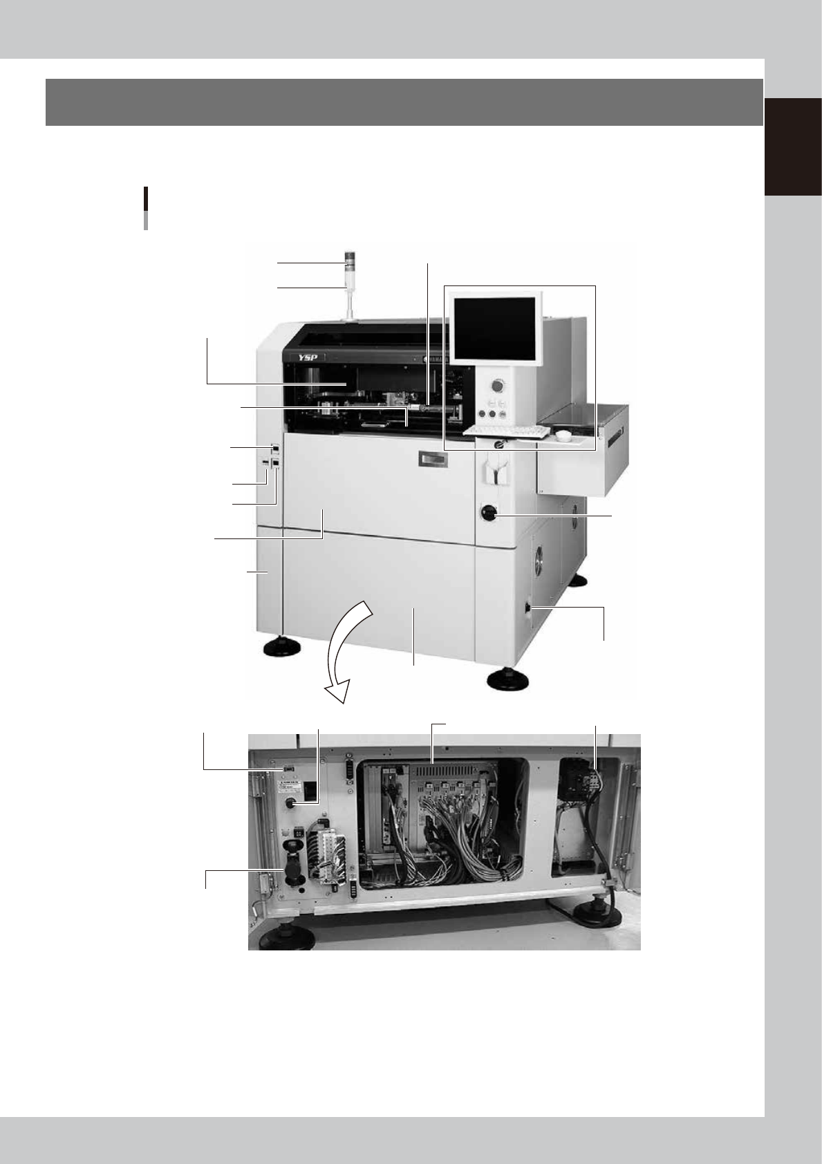
1. YSP main unit
A standard machine has the following configurations after installation. Names and functions of major parts
of the main unit are described on the subsequent pages.
YSP main unit
Front view
Signal light
Operation panel and data input unit
Power switch
Upper door (safety cover)
Edge clamp
pressure gauge
Cleaner vaccum
pressure gauge
Pressure gauge
Front lower panel
Conveyor unit
(below printing table)
Air supply/exhaust switch
Controller
Printing section
(Squeegee head, printing table)
I/O signal connector
(both left and right sides)
Buzzer
Pressure regulator (for air supply)USB port
Power connection terminals
Front panel
Front lower left panel
63101-L3-10