YSP_Users_E.pdf - 第264页
E-2 Printing guide 2. Data and condition setting 2.1 Material and setup information Material and setup information 1 2 3 4 6 8 5 64E03-L3-10 1 Enter board size data. Enter accurate size data (X, Y , height) of the board …
E-1
Printing guide
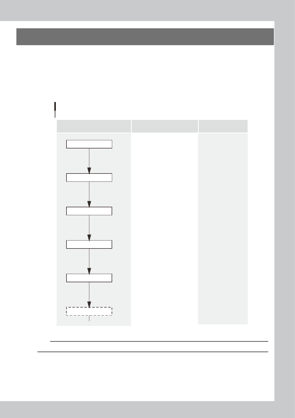
1. Flow of printing condition setting
The following diagram shows the flow of the condition setting (data setting) and the setup work necessary to
perform the printing with excellent quality.
•
Before starting the condition setting, it is necessary that the basic data input and the setup work have been completed.
•
The parameter change results after completion of the condition setting may slightly vary depending on the solder and/
or mask status.
•
It is recommended to first perform the test print with the default values and gradually narrow the conditions from the
test print results.
Printing condition setting
Contents of work Items to be set Related troubles
Setup work
Basic data input
・Alignment offsets X, Y, R
・Board size
・Mask information
・Squeegee type
・Edge clamp pressure
・Fiducial position coordinates
・Backup jig setting
・Board clamp status check
・Mark information check
Print deviation
Solder spread
Solder bridge
Print deviation
Solder enlargement
Solder chipping, mask remaining
Solder spread, solder bridge
Blur
Scraping trouble
Insufficient filling
・Squeegee pressure
・Squeegee speed
・Attack angle
・Board separation speed
・Board separation distance
・Alignment offset Z
・Solder supply interval
Solder chipping, mask remaining
Solder spread, solder bridge
・Cleaning interval
・Cleaning repeat
・Cleaning speed
Alignment offset
Cleaning conditions
Printed status check
Graphic alignment
Test print
Rolling
63E10-L3-00
n
NOTE
For more details about work procedures and contents of each parameter, see the relevant sections of this manual.
E-2
Printing guide
2. Data and condition setting
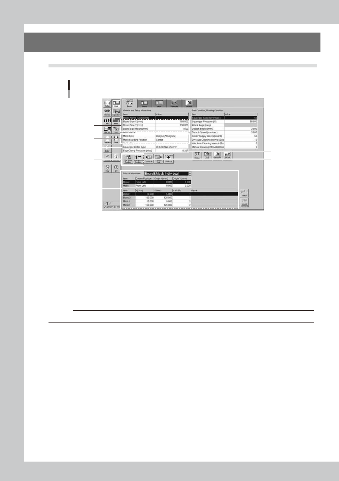
2.1 Material and setup information
Material and setup information
1
2
3
4
6
8
5
64E03-L3-10
1
Enter board size data.
Enter accurate size data (X, Y, height) of the board to be printed.
X : Sets the main stopper position.
Y : Sets the conveyor width.
Height : Sets the backup height.
2
Enter mask information.
1. Select a size of the mask to be used.
2. Select a mask standard position (standard position during the mask processing) (center or front
position).
c
CAUTION
In the YSP, you cannot use the rear position. Always select either the center or front position.
3
Select a squeegee type.
Select a type and size of the squeegee to be used. Each squeegee type has the features described
below.
Urethane squeeze : If the squeegee pressure level is too high, the squeegee is deformed, causing the
solder to be scraped away too much.
Metal squeeze : This metal squeegee is not deformed by the squeegee pressure. pressure and is less
affected by the squeegee pressure.
4
Set the backup jig.
e
1. Press the [SW. Prod. Pos.] button and check that the conveyor has moved to the setup position.
2. Press the [Conv. MS Axis Pos.] button and check that the main stopper has moved to the correct
position.
3. Press the emergency stop button and set the backup jig on the matrix plate.

E-3
Printing guide
5
Check the board clamp status.
1. Press the [Convey In] button. Follow the instructions that appear on the operation screen to load a
board.
2. When the board is clamped, check the following points.
•
Check the board for warpage or floating.
•
Push downward on the board to check that no part of the board is depressed.
•
Check that the upper surface of the conveyor is flush with the upper surface of the board.
6
Change the edge clamp pressure level.
If any trouble is found in the board clamp stated in Step 5, change the edge clamp pressure level.
Generally, if the edge clamp pressure level is too strong to the board, the board may be warped.
Conversely, if the edge clamp pressure level is too weak, this may cause the board to rattle.
7
Set the mask.
With the mask kept in contact with the set position, turn ON the CLAMP switch to clamp the mask.
For more details about the set position, see "2. Compatible masks" in the Appendix of this manual or the
labels affixed to the machine.
8
Set fiducial mark information.
1. Select either the [Board & Mask Common] or [Board & Mask Individual] designation for the datum
position, position coordinates, and mark type of each fiducial mark.
2. Select the board and mask datum positions, and enter origin offset amounts from the datum
positions.
3. Enter mark Nos. used to recognize the correct fiducial mark positions on the board and mask.
4. Press the [Mark] button to create mark information.
n
NOTE
When the mark information has already been created, press the [Teach] button to check that the fiducial mark
positions are correct.
To check the fiducial mark positions, select [Board 1] or [Board 2] for the board fiducial mark or [Mask 1] or [Mask 2] for
the mask fiducial mark, and then press the [Teach] button.