YSP_Users_E.pdf - 第153页
4-50 4 Creating and setting the data 2. On the manual board check screen, select the coordinate from which you want to start checks. 3. Press the [Trace] button to start visual checks. The printed state at the selected c…
4-49
4
Creating and setting the data
3
Check that test print begins.
After mark recognition is complete, the conveyor table moves to printing position and is fixed, and the
squeegee head automatically begins moving to make a test print.
4
When the test print is complete, unload the board
Follow the message on the screen to unload the board.
n
NOTE
When you are going to make visual check of the test print state on the operation display, leave the board clamped
on the conveyor and advance to the next step.
5
Check the printed state.
e
l
When the board was unloaded from the conveyor:
Press the emergency stop button, take the board out of the conveyor and visually check the printed
state.
l
When the board was left clamped on the conveyor:
Make a visual check on the operation display as explained below.
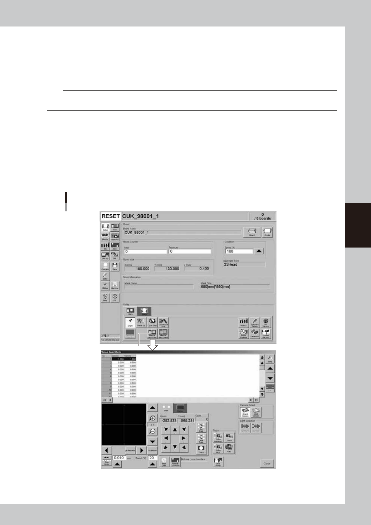
1. Open the [Utility] tab on the Setup screen and press the [Manual Board Check] button.
The manual board check screen appears.
[Manual Board Check] button
[Manual Board Check] button
64449-L3-00
4-50
4
Creating and setting the data
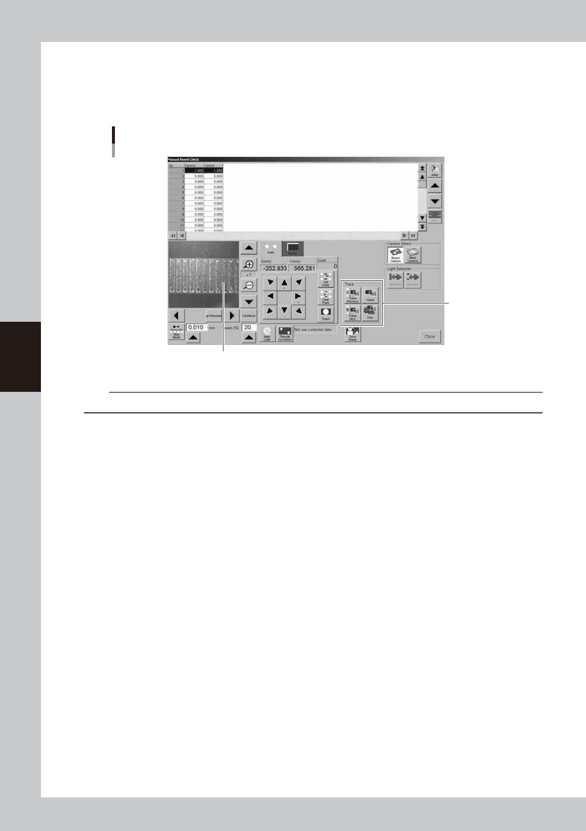
2. On the manual board check screen, select the coordinate from which you want to start checks.
3. Press the [Trace] button to start visual checks.
The printed state at the selected coordinate is displayed on the vision display. Check the position
and area of the printed solder versus the land pattern. Using the [Auto] button allows continuous
trace of the inspection coordinates that were set.
Manual board check screen
[Trace] button
Printed state is displayed.
64450-L3-00
n
NOTE
When using the trace function to make visual checks, the inspection coordinates must be entered beforehand.
l
Solder scraping trouble or missing solder trouble
Check the settings for printing motion. Refer to the "Printing Guide" at the end of this manual for how to set the
"Squeegee pressure" and "Squeegee speed" parameters.
Printing position deviations are described in the next step.
4-51
4
Creating and setting the data
6
Adjust the print position errors.
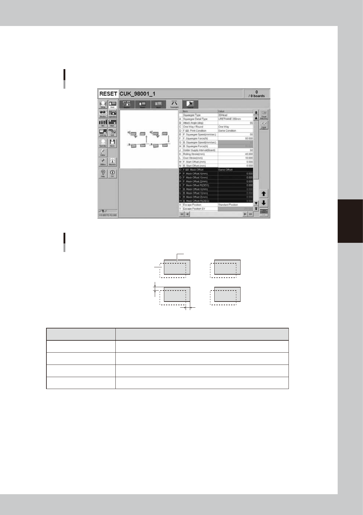
Open the [Print]-[Squeegee] tab and adjust the following parameters.
Enter the positional offsets in the Mask Offset X, Y and R parameters according to the position errors.
(Mask Offset Z adjustment is not necessary here.)
[Print]-[Squeegee] tab
64451-L3-00
Mask Offset XY
Printed solder
Land pattern
Offset X
Offset Y
63431-L3-00
Printed state Offset entry
When shifted to right In Offset X, enter the position error (mm).
When shifted to left In Offset X, enter the position error (mm) with a minus sign.
When shifted to upper side In Offset Y, enter the position error (mm).
When shifted to lower side In Offset Y, enter the position error (mm) with a minus sign.