YSP_Users_E.pdf - 第142页
4-39 4 Creating and setting the data 7.5 Mark Adjust mode T his operation checks w hether the parameter settings are correct. F or parameters w hich are unspecified, the optimal values can be obtained b y performing &quo…
4-38
4
Creating and setting the data
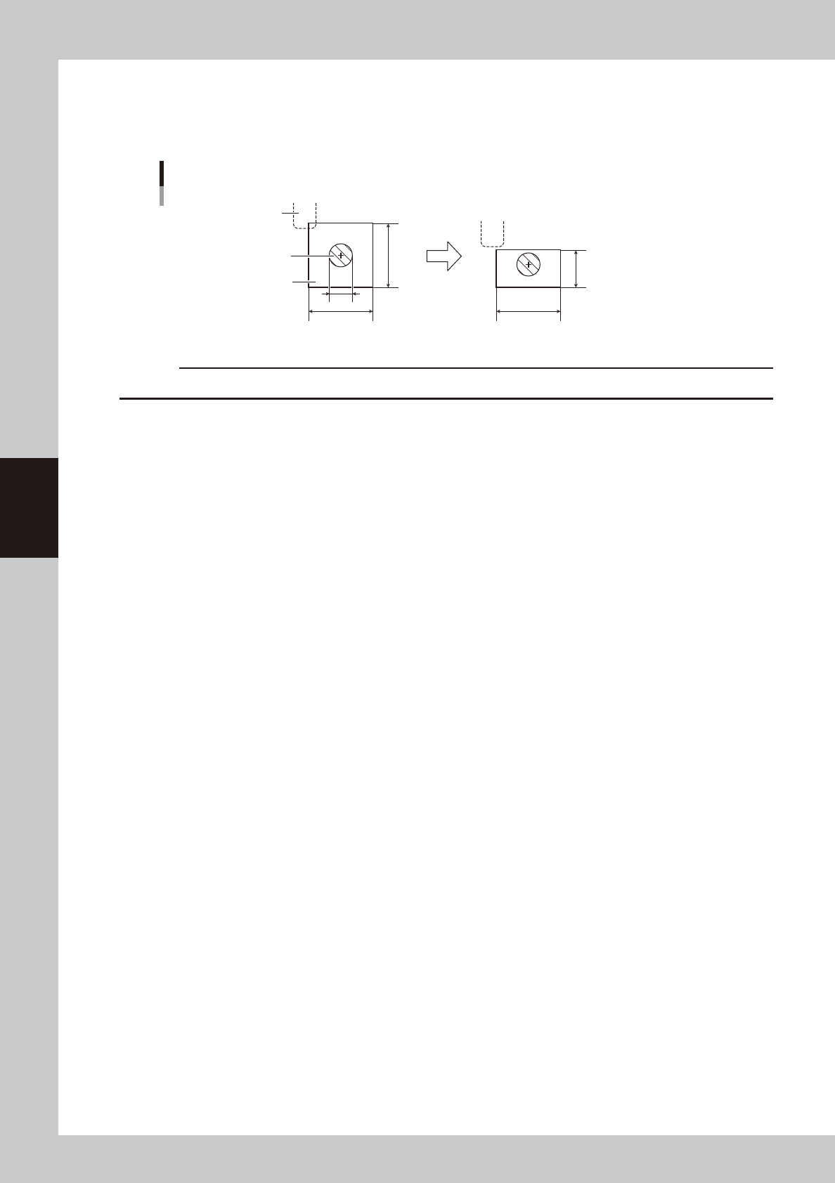
E, F: Search Area X, Search Area Y
As a general guide, set this parameter to the mark diameter plus 3mm. For example, when the mark diameter is 1mm, set
this parameter to "4mm" as shown below. If other marks (such as resist, silk print, other patterns) exist in this search area,
set the search area X and Y separately or make the "Search Area" setting smaller.
Pattern
1mm
4mm
4mm
4mm
2.5mm
Search Area
Search Area
Mark
63424-L3-00
c
CAUTION
When a "0" is entered in Mark Search Area Y, marks are recognized within the square of Mark Search Area X.
G to K: Light level
Lighting for recognizing a mark is divided into several zones. The light level in each zone is displayed here. Optimum
light levels can be found in the Mark Adjust mode explained later.
L, M: Cut Outer Noise, Cut Inner Noise
When the mark image is digitized and shown in binary (black and white), noise may appear outside or inside the mark.
In this case, adjusting these parameter values in the Mark Adjust mode (described later) can cut the noise.
4-39
4
Creating and setting the data
7.5 Mark Adjust mode
This operation checks whether the parameter settings are correct. For parameters which are unspecified, the
optimal values can be obtained by performing "VISION TEST" here.
1
Select the mark data.
In the data list on the Mark screen, line up the cursor with the mark data you want to check.
2
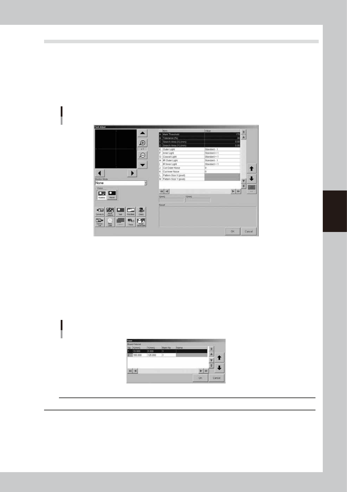
Press the [Mark Adjust] button to enter the Mark Adjust mode.
The Mark Adjust screen appears as shown below.
Mark Adjust screen
64433-E3-00
3
Set the board on the conveyor and clamp it.
To clamp the board, press the [Convey In] button and follow the message that appears.
When adjusting fiducial marks on a mask, clamp the mask on the printing table.
4
Perform a trace to the mark.
1. Press the [Trace] button to open the "Trace" dialog box.
2. Press the [OK] button to perform a trace to the selected mark position.
For board fiducial marks, the board moves to a point just under the board vision camera. For mask
fiducial marks, the mask vision camera moves to a point directly under the mark on the mask frame.
Trace dialog box
64434-L3-00
TIP
For details on the trace and teaching functions, see "1. Teach and trace" in Chapter 6.
4-40
4
Creating and setting the data
5
Check the trace position.
Check that the mark is aligned with the center of the vision monitor, at the point shown below. If the
position has shifted, open the [Print]-[Board] tab (or [Print]-[Mask] tab) and reteach the mark
coordinate.
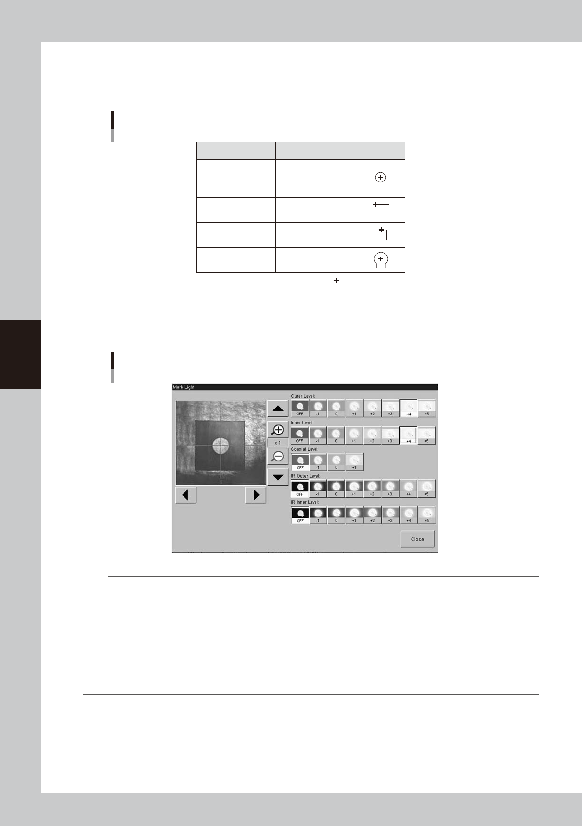
Mark trace position
Shape Type Teaching point Example
Circle, Square
Triangle, Sp. Shape
Center of mark
Corner of mark
Center of a square
edge line
Center of a round edge
Corner
TopEdge
CirEdge
: Center of crosshairs
63425-L3-00
6
Adjust the light levels.
Press the [Light] button to open the light level adjustment screen, and adjust the light level in each
lighting zone so that the mark can be most clearly viewed on the vision monitor.
Light level adjustment
64435-L3-00
TIP
Optimum light levels depend on the materials of the board, mask frame and mark. Use the following method to find
optimum light levels.
1. Turn off all light units.
2. Turn on, one at a time, "Outer Light", "Inner Light", "Coaxial Light, "IR Outer Light" and "IR Inner Light" at the
maximum level, to see how clearly the mark can be seen.
3. Combine the light units that were effective, and adjust their light levels.
As a general guide for adjusting board mark lighting, try these suggestions.
• Flat surface marks reflecting light : "Coaxial Light" is effective.
• Flat surface marks made of copper oxide : "IR Inner Light" is effective.
• Marks with uneven surface diffusing light : "IR Outer Light" is effective.