YSP_Users_E.pdf - 第260页
A-9 A Appendix 4. Board suppor t jig combinations Board support jig dimensions and combination table Front of machine (89mm, 15 rows of pin insertion holes) (33mm, 5 rows of pin insertion holes) (19mm, 3 rows of pin inse…
A-8
A
Appendix
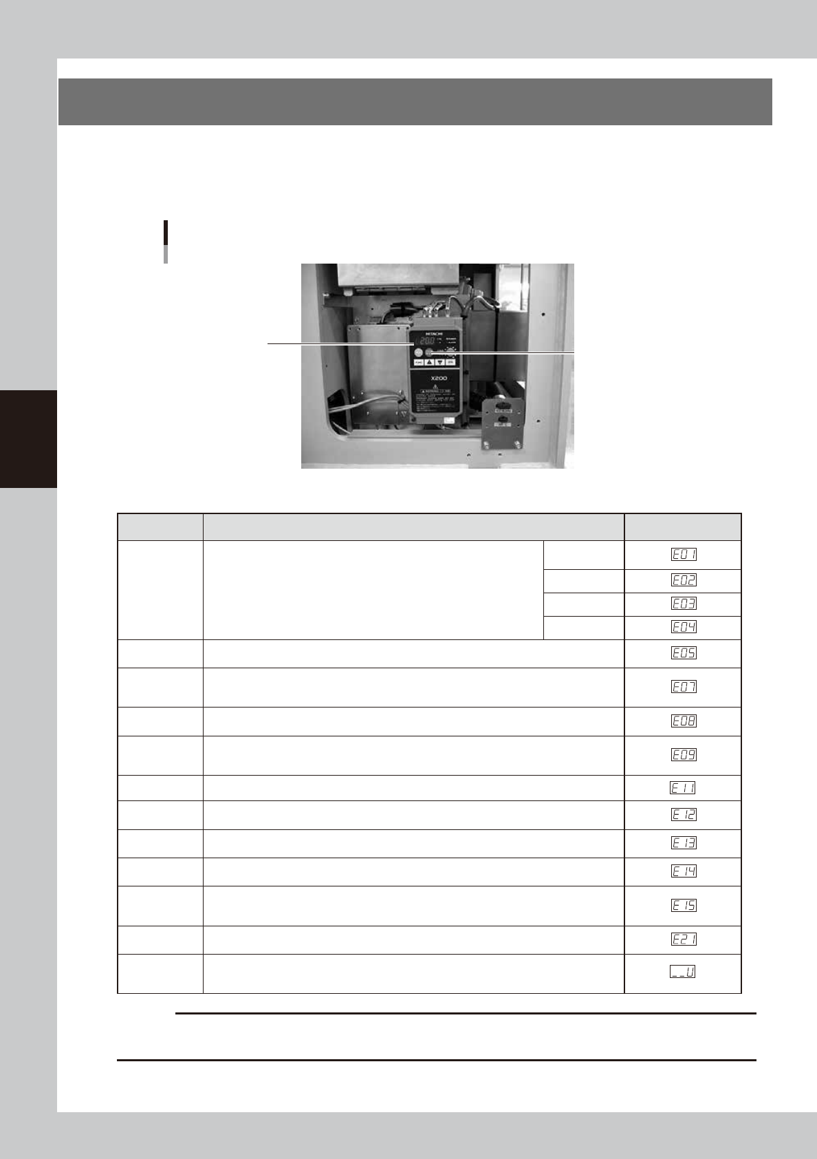
3. Inverter (suction unit)
The suction unit built into the YSP uses an inverter to ensure stable operation.
If a problem occurs with the inverter or suction unit, an error message appears on the YSP operation display.
In this case, check the error number shown on the inverter display panel and contact our sales office or sales
representative.
Inverter
Located behind the right panel on the rear of the machine.
Inverter display panel
Reset button
63014-L3-00
n
Inverter error display
Name Description Error display
Overcurrent
protection
When the motor is restrained or suddenly reduced in speed, a large
current is charged to the inverter, causing a fault. When the inverter
detects 205% peak current of the inverter, an overcurrent occurs.
Constant
speed
Deceleration
Acceleration
Others
Overload
protection
When the inverter output current causes the motor to overload, the electronic thermal
trip in the inverter cuts off the inverter output.
Overvoltage
protection
If regenerative energy from the motor or the main power supply voltage is high,
the protective circuit activates to cut off the inverter output when the voltage of the
converter section exceeds the specification.
EEPROM
error
The inverter output is cut off when EEPROM in the inverter has an error due to external
noise, excessive temperature rise, or other factor.
Undervoltage
protection
When the input voltage received by the inverter decreases, the control circuit does not
function normally. When the input voltage is below the specification, the inverter output
is cut off.
CPU error The inverter output is cut off when the inverter CPU has a malfunction or an error.
External trip
When the external equipment or unit has an error, the inverter receives the
corresponding signal and cuts off the output.
USP error
The USP error is indicated when the power is turned on with the inverter in the RUN
state. (Enabled when the USP function is selected.)
Ground fault
protection
GROUND fault is detected between the inverter output section and the motor when the
power is turned on, to protect the inverter.
Input
overvoltage
protection
When the input voltage is higher than the specified value, it is detected 100 seconds
after power is turned on and the output is cut off.
Temperature
error
When the temperature in the main circuit increases due to cooling fan stop, the inverter
output is cut off. (Only for the model type with cooling fan)
Waiting on
account of
undervoltage
Waiting with the output turned off, because the inverter receiving voltage has dropped.
c
CAUTION
1. Press the reset key 10 seconds after the alarm has occurred.
2. If an EEPROM error occurs, be sure to comfirm the seting value again.
A-9
A
Appendix
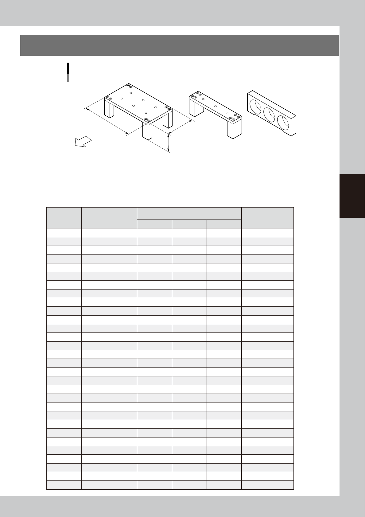
4. Board support jig combinations
Board support jig dimensions and combination table
Front of machine
(89mm, 15 rows of pin insertion holes) (33mm, 5 rows of pin insertion holes) (19mm, 3 rows of pin insertion holes)
A B C
W
L : 159mm
H : 55mm
63010-L3-00
The table below shows how many A to C blocks are arranged in the W direction and how many pin rows are
used for each board size.
Combine blocks and pins suitable for the board size while referring to the table below.
n
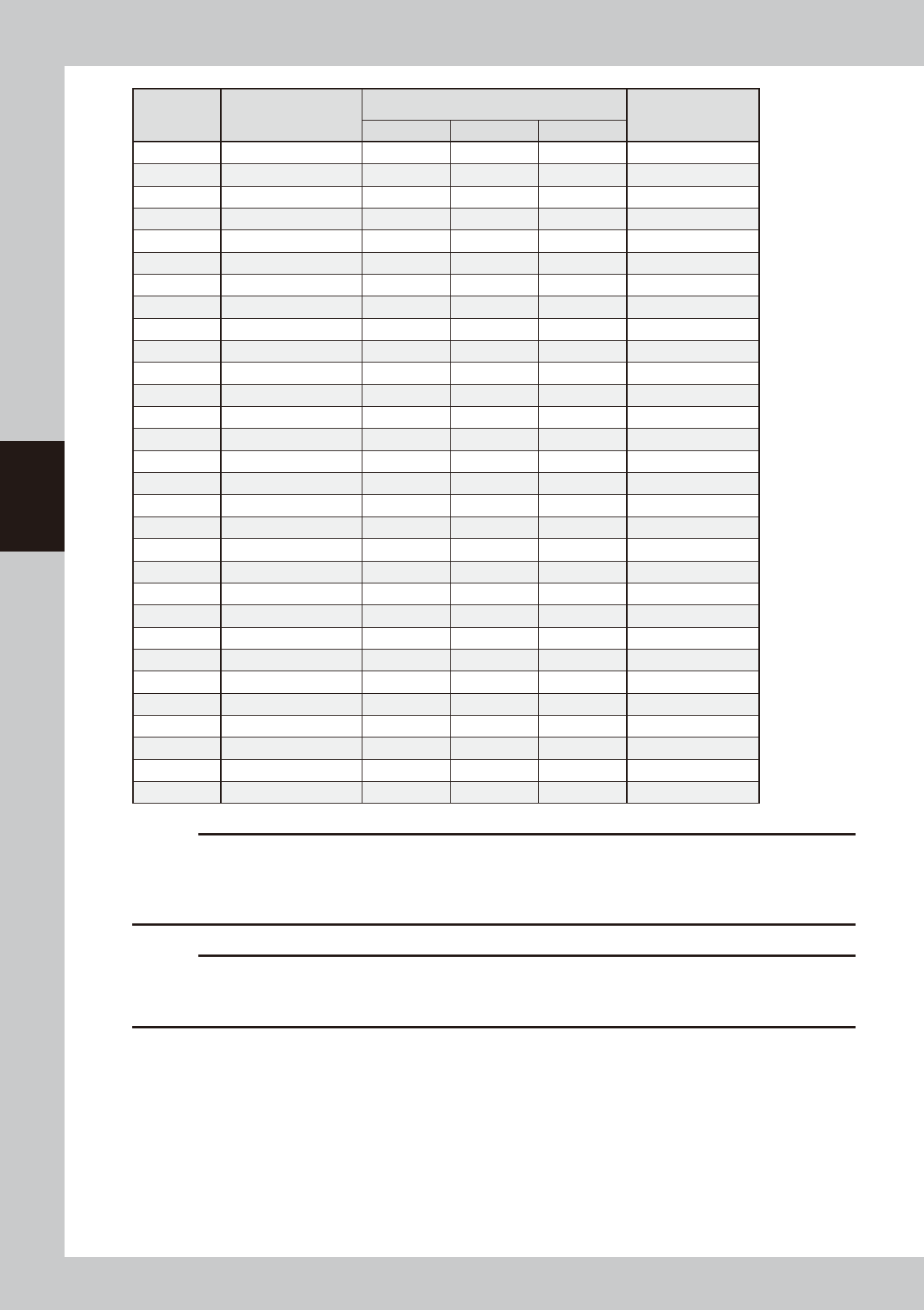
Board support jig combination table
Number of
rows
Applicable board size
(W)
Board support jig type/Q'ty used
Pins combined
(rows)
A B C
5 50 to 52 0 1 0 0
6 52 to 59 0 0 2 0
7 59 to 66 0 0 2 1
8 66 to 73 0 1 1 0
9 73 to 80 0 1 1 1
10 80 to 87 0 2 0 0
11 87 to 94 0 2 0 1
12 94 to 101 0 1 2 1
13 101 to 108 0 2 1 0
14 108 to 115 0 2 1 1
15 115 to 122 1 0 0 0
16 122 to 129 0 2 2 0
17 129 to 136 0 2 2 1
18 136 to 143 1 0 1 0
19 143 to 150 1 0 1 1
20 150 to 157 1 1 0 0
21 157 to 164 1 0 2 0
22 164 to 171 1 0 2 1
23 171 to 178 1 1 1 0
24 178 to 185 1 1 1 1
25 185 to 192 1 1 1 2
26 192 to 199 1 1 2 0
27 199 to 206 1 1 2 1
28 206 to 213 1 2 1 0
29 213 to 220 1 2 1 1
30 220 to 227 2 0 0 0
31 227 to 234 1 2 2 0
32 234 to 241 1 2 2 1
33 241 to 248 2 0 1 0
34 248 to 255 2 0 1 1
A-10
A
Appendix
Number of
rows
Applicable board size
(W)
Board support jig type/Q'ty used
Pins combined
(rows)
A B C
35 255 to 262 2 1 0 0
36 262 to 269 2 1 0 1
37 269 to 276 2 1 0 2
38 276 to 283 2 1 1 0
39 283 to 290 2 1 1 1
40 290 to 297 2 2 0 0
41 297 to 304 2 2 0 1
42 304 to 311 2 2 0 2
43 311 to 318 2 2 1 0
44 318 to 325 2 2 1 1
45 325 to 332 3 0 0 0
46 332 to 339 3 0 0 1
47 339 to 346 3 0 0 2
48 346 to 353 3 0 1 0
49 353 to 360 3 0 1 1
50 360 to 367 3 1 0 0
51 367 to 374 3 1 0 1
52 374 to 381 3 1 0 2
53 381 to 388 3 1 1 0
54 388 to 395 3 1 1 1
55 395 to 402 3 2 0 0
56 402 to 409 3 2 0 1
57 409 to 416 3 2 0 2
58 416 to 423 3 2 1 0
59 423 to 430 3 2 1 1
60 430 to 437 3 2 1 2
61 437 to 444 3 2 2 0
62 444 to 451 3 2 2 1
63 451 to 458 3 2 2 2
64 458 to 460 3 2 2 3
c
CAUTION
The board support jig is secured by press-fitting it into the holes in the matrix plate. Mount the board support jig after
checking that no solder or foreign matter exists on the matrix plate.
Additionally, if the board support jig is placed so that it protrudes from the matrix plate, this may cause damage to the
machine.
c
CAUTION
The board support jigs explained in this section are specially designed for the YSP. If these board support jigs are used
for other machine, this may cause serious damage to the machine.
Therefore, never use these board jigs for a machine other than the YSP.