YSP_Users_E.pdf - 第276页
S-1 INDEX Index A Safety instructions Cautions during power outage iv Cautions regarding ferromagnetic fields iv CE marking i Components and materials to be used x Handling batteries ix Handling grease and oil ix Handling…
E-13
Printing guide
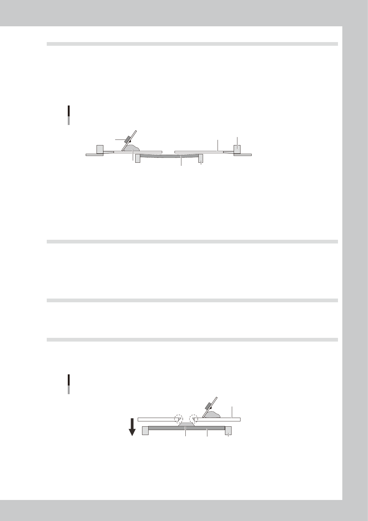
4.4 Solder spread, solder bridge
n
Backup jig (For matrix pin)
If the matrix pin positions are not appropriate or the number of pins is insufficient, the board is depressed by the printing
pressure, resulting in a gap between the board and mask.
n
Alignment offset Z
The offset value in the Z direction (clearance between the board and mask) is too large.
Mask clearance
Solder
Board
Mask
Squeegee
Conveyor
Mask frame
63E03-L3-10
n
Cleaning interval
The printing is performed with the backside of the mask contaminated by solder since the cleaning interval is long.
n
Cleaning repeat
The solder contamination on the backside of the mask cannot be wiped away completely with the set cleaning repeat
cycles.
4.5 Scraping trouble
n
Squeegee pressure
The squeegee pressure is too low with respect to the squeegee speed and attack angle settings.
n
Printing pressure
The printing pressure level is too low to the set squeegee speed and attack angle.
4.6 Solder enlargement
n
Board separation speed
Both ends of the printed solder are enlarged since the board separation speed is slow.
4.7 Solder chipping, mask remaining
n
Board separation speed
Since the board separation speed is too fast, the board is separated with the solder sticking to the mask.
Mask remaining
Solder
Board
Mask
Conveyor
Excessively high speed
63E04-L3-00
n
Board separation distance
The conveyor starts moving even though the board is not separated completely since the board separation distance is
short.

S-1
INDEX
Index
A
Safety instructions
Cautions during power outage iv
Cautions regarding ferromagnetic fields iv
CE marking i
Components and materials to be used x
Handling batteries ix
Handling grease and oil ix
Handling heavy objects ix
Handling solvents vii
Handling the laser viii
Lock out the main switch and the air supply/
exhaust switch iii
Muzzle plate vi
Operator and service personnel iii
Safety ii
Safety message and categories xi
Typical warning text xii
Warning labels xv
[Adjust] button 6-11
Air regulator unit A-1
Air supply/exhaust switch 1-1
Automatic stop 3-21
B
Backup
Making a backup of system data 5-6
[Backup] button 5-9
Basic data setting 4-3
Basic operation
Canceling emergency stop 2-1
Clearing an error 2-2
Starting the machine 2-10
Turning off the machine 2-12
[Board] button 3-4
Board check positions 4-10
Board clamp unit 1-10
Board data
Creating new data 4-1
Selecting the board data 3-4
Board data setting 4-5
Alignment 4-9
Board Datum Position 4-7
Board Size 4-6
Mark No. 4-12
Name 4-12
Origin 4-7
Print Feedback 4-9
Spin Timer 4-7
X, Y 4-6
Board distortion offset 4-10
board production
Finishing board production 3-21
Starting board production 3-14
Board support jig combinations A-9
Board support jigs 1-12
[BUZZER OFF] button 2-2
C
Camera unit 1-20
CD-ROM drive 1-1
Cleaner data setting 4-28
Board count control 4-28
Dry Auto Interval 4-28
Dry Auto Repeat 4-28
Dry Auto Speed 4-28
Manual Interval 4-28
Time interval control 4-30
Wet Auto Interval 4-28
Wet Auto Repeat 4-28
Wet Auto Speed 4-28
Cleaning unit 1-18
Connection between machines A-2
Consumable parts 7-1
[Convey In] button 3-6
Conveyor unit 1-10
Conveyor unit setup 3-5
[Convey-out Stop] button 3-21
[Create] button 4-1
Cursor teaching 6-6
[Cycle Stop] button 3-21
D
Daily inspection 8-2
Daily operation flow 3-1
Data backup 5-1
Database 5-16
E
Emergency stop 2-1
Canceling emergency stop 2-1
Emergency stop button 3-21
Error
Clearing an error 2-2
Errors and troubleshooting 2-3
[ERROR CLEAR] button 1-5,2-2
Extended exit conveyor 1-15
F
FullASCII Output 5-25
[Full Backup] button 5-10
G
Gauze roll 1-18,7-6
Replacing the gauze roll 7-6
Graphic alignment 4-42
H
Handle 1-7
I
Inspecting before operation 2-9
Inspection and maintenance 8-2
Inverter A-8
K
Keyboard 1-6
L
[Light] button 4-40
Lighting level 6-4
Light level 4-40
Liquid crystal touch screen 1-6
Local fiducial function 4-11
M
[Main Stopper Position] button 3-5
Manual axis movement 6-19
Manual operation 6-17
Mark Adjust mode 4-32
[Mark] button 4-33
Mark data 4-32
Algorithm Type 4-37,6-11
Creating procedure 4-33
Cut Inner Noise 4-38
Cut Outer Noise 4-38
Light level 4-38
Mark Area 4-36
Mark Out Size 4-36
Mark Threshold 4-37
Mark Type 6-10
Outline 4-36
Search Area 4-38
Shape Type 4-35
Surface Type 4-37
Threshold level 4-41
Tolerance 4-37
Using the pattern matching 6-15
Mark data parameters 4-32
Mask 1-7
Compatible masks A-6
Mask adaptor 3-9
Mask check positions 4-17
Mask clamp 1-7
Mask clamp switch 1-7
Mask data setting 4-13
Mark No. 4-14
Mask Datum Position 4-16
Mask Name 4-15
Mask Origin 4-16
Mask parameters 4-15
Mask Size 4-15
Mask Standard Position 4-15
Mask Vacuum 4-16
Name 4-14
Standard Position Offset 4-15
X, Y 4-14
Mask frame dimensions A-7
Mask Offset XY 4-51
Mask size A-6
Mask standard position A-7
Mask stopper pin A-6
Matrix pin arrangement 6-16
Matrix pins 1-11
[Monitor] button 3-15
[Monitor]-[Detail] tab 3-16

S-2
INDEX
[Monitor]-[Filling] tab 3-20
[Monitor]-[Vision] tab 3-17
Mouse 1-6
"Move Axis" screen 6-18
[Move Squeegee] button 3-8
N
NEXT INTERFACE connector A-4
O
[Off] button 2-12,3-22
Operation panel 1-4
Operation panel buttons 1-5
Operation screen 2-14
[Operator] button 2-11
P
Page layout iii
Part names and functions 1-1
[Pattern] button 6-12
Pattern matching 6-15
Pattern registration 6-10
Periodic inspection 8-3
Point teaching 6-3
Power connection A-5
Precautions
Inspection and maintenance 8-1
Replacing consumable parts 7-1
PREVIOUS INTERFACE connector A-3
[Print]-[Board] tab 4-5
[Print]-[Cleaner] tab 4-28
Printing section 1-7
[Print]-[Mask] tab 4-13
[Print]-[Squeegee] tab 4-19
Production log 5-18
R
[READY] button 1-5,2-1
Refilling the cleaning solvent 7-10
[RESET] button 1-5
Restoring the system data 5-11
Restoring a system backup 5-11
Restoring a system full backup 5-13
Return-to-origin 2-10
[Rolling] button 3-11
Rolling dialog box 3-12
Rolling operation 3-11
S
[Save] button 4-2
Servo-controlled axes 1-21
Setup screen 3-4
Signal light 1-2
Solvent tank 1-18
Squeegee
3S squeegee 1-8
Double squeegee 1-9
Squeegee data setting 4-19
B. Mask Offset 4-23
B. Squeegee Force 4-20
B. Squeegee Speed 4-20
Escape Position 4-23
F. & B. Mask Offset 4-22
F. & B. Print Condition 4-20
F. Mask Offset 4-23
F. Squeegee Speed 4-20
One Way/Round 4-20
Rolling Stroke 4-21
Solder Supply Interval 4-20
Squeegee Type 4-19
Squeegee head 1-7
Squeegee holder 1-7
[START] button 1-5
[STOP] button 1-5,3-21
Suction unit 1-19
[SW. Prod. Position] button 3-5
T
Teach and trace 6-1
Cursor teaching 6-6
Multi-point input 6-5
One-point input 6-4
Teach screen 6-2
Teach (trace) screen 6-8
[Test Print] button 4-48
Touch screen 8-2
Trace 6-8
[Trace] button 6-2,6-8
U
[Unit]-[Cleaner] tab screen 6-23
[Unit]-[Conveyor] tab 3-5
[Unit]-[Conveyor] tab screen 6-20
[Unit]-[I/O] tab screen 6-24
[Unit]-[Mask] tab screen 6-21
Unit screen 6-17
[Unit]-[Squeegee] tab screen 6-22
W
Warm-up 3-2
[Warm Up] button 3-2
Y
YSP main unit 1-1