YSP_Users_E.pdf - 第266页
E-4 Printing guide 2.2 Alignment of fset setting Alignment offsets [Visual Matching] button 64E04-L3-10 Press the [Visual Matching] button to open the Alignment Offset screen. Determine each offset value while carefully …
E-3
Printing guide
5
Check the board clamp status.
1. Press the [Convey In] button. Follow the instructions that appear on the operation screen to load a
board.
2. When the board is clamped, check the following points.
•
Check the board for warpage or floating.
•
Push downward on the board to check that no part of the board is depressed.
•
Check that the upper surface of the conveyor is flush with the upper surface of the board.
6
Change the edge clamp pressure level.
If any trouble is found in the board clamp stated in Step 5, change the edge clamp pressure level.
Generally, if the edge clamp pressure level is too strong to the board, the board may be warped.
Conversely, if the edge clamp pressure level is too weak, this may cause the board to rattle.
7
Set the mask.
With the mask kept in contact with the set position, turn ON the CLAMP switch to clamp the mask.
For more details about the set position, see "2. Compatible masks" in the Appendix of this manual or the
labels affixed to the machine.
8
Set fiducial mark information.
1. Select either the [Board & Mask Common] or [Board & Mask Individual] designation for the datum
position, position coordinates, and mark type of each fiducial mark.
2. Select the board and mask datum positions, and enter origin offset amounts from the datum
positions.
3. Enter mark Nos. used to recognize the correct fiducial mark positions on the board and mask.
4. Press the [Mark] button to create mark information.
n
NOTE
When the mark information has already been created, press the [Teach] button to check that the fiducial mark
positions are correct.
To check the fiducial mark positions, select [Board 1] or [Board 2] for the board fiducial mark or [Mask 1] or [Mask 2] for
the mask fiducial mark, and then press the [Teach] button.
E-4
Printing guide
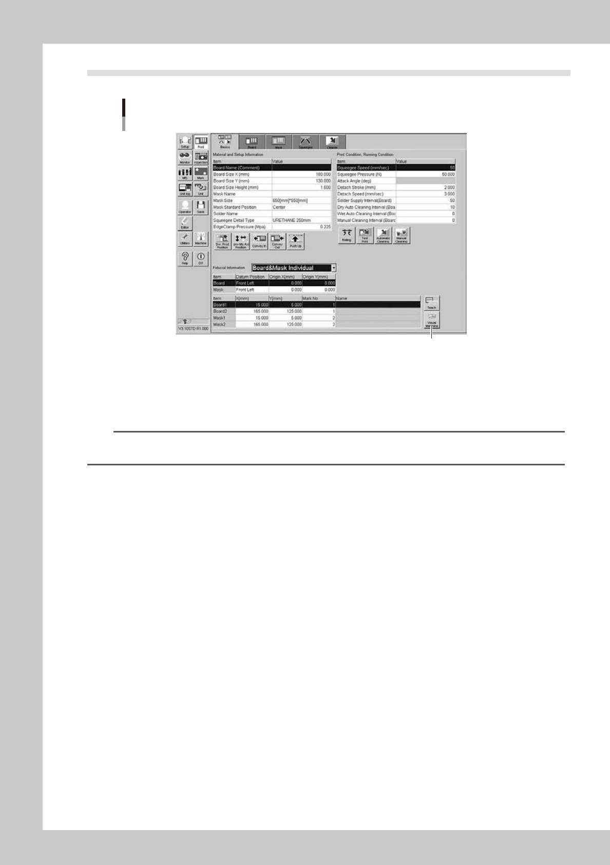
2.2 Alignment offset setting
Alignment offsets
[Visual Matching] button
64E04-L3-10
Press the [Visual Matching] button to open the Alignment Offset screen. Determine each offset value
while carefully checking the screen.
Since the graphic alignment is used for this alignment offset setting, set values in the [Mask Offset
X(mm)], [Mask Offset Y(mm)], and [Mask Offset R(DEG)] fields you can check on the screen.
n
NOTE
For more details about how to correctly use the graphic alignment, see Chapter 4, “Graphic alignment”, in this
manual.
E-5
Printing guide
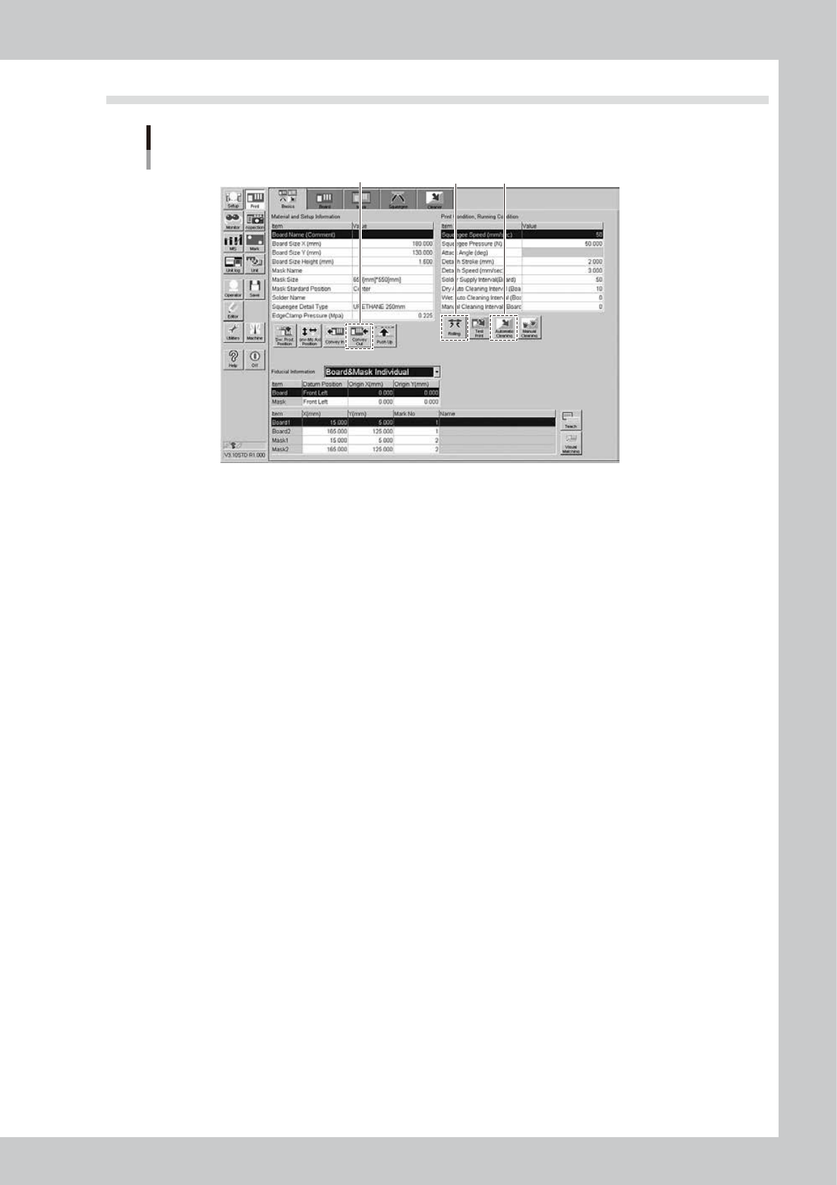
2.3 Rolling
Rolling
2 4
3
64E05-L3-10
1
Set the squeegee to be used.
2
Start the rolling operation.
1. Press the [Rolling] button, and follow the messages that appear on the operation screen to align the
board and mask positions. After the positions have been aligned completely, supply the solder. The
reference solder supply volume is one pod for a squeegee size of 530 mm. Based on this reference
volume, finely adjust the solder supply volume in accordance with the squeegee size.
2. Start the rolling. At this time, the squeegee pressure, squeegee speed, and attack angle are left set
at their default values.
3
Visually check the rolling condition.
l
If the solder slips:
If the rolling is not performed correctly due to solder slippage, decrease the squeegee speed.
l
If the scraped solder remains on the mask apertures:
Increase the printing pressure level or decrease the squeegee speed.
When no problem is found in the rolling and solder scraping condition, end the rolling operation.
4
Unload the board.
Press the [Convey Out] button, and follow the messages that appear on the operation screen to unload
the board.
5
Perform the auto cleaning.
Press the [Automatic Cleaning] button, and follow the instructions that appear on the screen to perform
the auto cleaning.