YSP_Users_E.pdf - 第271页
E-9 Printing guide 3.4 Squeegee (Rolling) 3.4.1 Squeegee speed n Function T his parameter sets a squeegee movement speed. n Setting range and initial value T his parameter can be set in a range of 1 to 200mm/sec. T he in…
E-8
Printing guide
3.1.2 Backup jig
n
Function
This jig supports a board from the bottom when it is clamped.
n
Setting procedures
There are three kinds of backup jigs as described below.
• Matrix pin : Used with the push-up pins inserted into the matrix plate. (Printing of B-surface of double
sided mounted board, etc.)
• Flat surface backup : Used with the blocks (support jigs) placed on the matrix plate. (Mounted board with one
flat side)
• Vacuum gripper backup : Used for boards having a height of 0.5mm or less. (This backup is set on the [Board] tab
screen.)
n
NOTE
Matrix pins and flat surface backup can be used together to support a board.
3.2 Board and mask mark recognition (Mark position)
n
Function
These parameters set coordinates of the fiducial mark positions of the board and mask. The camera moves to the mark
position to recognize the fiducial mark so as to align the board and mark positions.
n
Setting procedures
Enter accurate coordinates based on the CAD data of the board and mask.
3.3 Alignment offset
n
Function
Normally, the board and mask mark positions are set with the CAD data. Therefore, as each mark is recognized, the
board pattern is aligned with the mask apertures precisely. However, if any deviation, such as elongation of board
occurs, these offset values are used to correct this deviation.
n
Setting procedures
Offset values can be set in the X, Y, Z, and R directions.
To set offset values in the X, Y, and R directions, press the [Visual Matching] button on the [Basics] tab screen to set them.
n
NOTE
You cannot set the offset values in the Z direction with the graphic alignment. Check the contact status between the
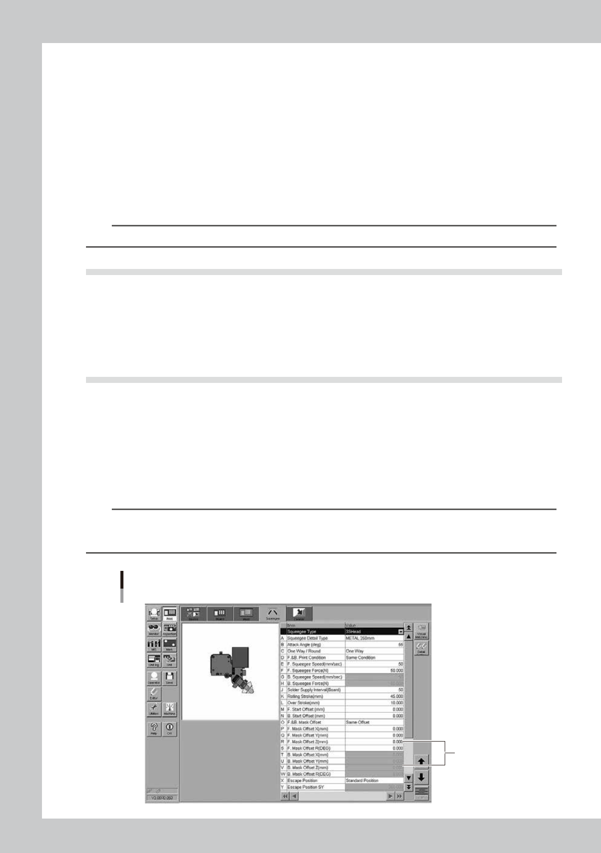
mask and board during the rolling test. Enter appropriate values in the [Mask Offset Z] fields on the [Squeegee] tab
screen directly.
Alignment offset Z
Enter values
in these fields.
64E02-L3-00
E-9
Printing guide
3.4 Squeegee (Rolling)
3.4.1 Squeegee speed
n
Function
This parameter sets a squeegee movement speed.
n
Setting range and initial value
This parameter can be set in a range of 1 to 200mm/sec.
The initial value is 50mm/sec.
n
Setting procedures
Set a speed at which the solder does not slip on the mask while carefully checking the rolling status.
If the solder scraping on the mask is insufficient, decrease the speed.
3.4.2 Squeegee pressure
n
Function
This parameter sets a squeegee pressure level.
n
Setting range and initial value
This parameter can be set in a range of 1 to 200N.
The initial value is 50 N.
n
Setting procedures
Set this parameter corresponding to the solder scraping status on the mask.
Particularly, for the urethane squeegee, if the squeegee pressure level is too high, the solder is scraped away too much,
causing the filling volume to decrease. If the squeegee pressure level is too low, a scraping trouble occurs in both the
urethane and metal squeegees, resulting in an excessive solder trouble or a missing solder trouble.
n
NOTE
Use both "Squeegee speed" and "Squeegee pressure" to adjust the solder scraping.
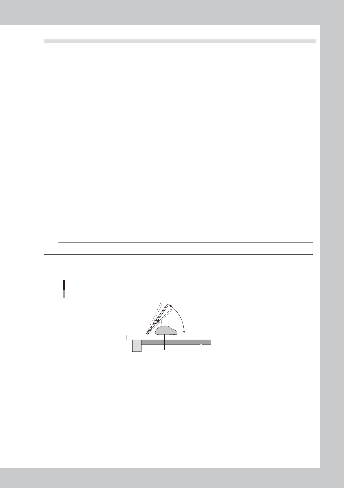
3.4.3 Attack angle (degree (°))
Attack angle
Solder
Attack angle
Board
Mask
55° (Default)
63E00-L3-00
n
Function
This parameter sets an attack angle (angle between the squeegee and mask).
n
Setting range and initial value
This parameter can be set in a range of 45 to 65°.
The initial value is 55°.
n
Setting procedures
Increasing the angle will decrease the solder filling volume. Conversely, decreasing the angle will increase the solder
filling volume.
E-10
Printing guide
About attack angle
The attach angle is normally used with its initial value except for special cases (examples described below).
•
If the viscosity is high and low, the attack angle needs to be increased and decreased, respectively as corrective
measures against the solder viscosity trouble.
•
The filling volume needs to be adjusted when printing at a high speed.
•
The filling volume needs to be finely adjusted for the metal squeegee.
•
If the filling pressure is needed, the attack angle is decreased to increase the filling pressure level.
3.5 Solder supply interval
n
Function
This parameter sets how many boards are printed by one solder supply operation.
n
Setting range and initial value
This parameter can be set in a range of 0 to 9999 boards.
The initial value is 50 boards.
n
Setting procedures
The number of boards to be input is determined from the ratio of solder consumption per board (gram) to solder supply
volume.
Normally, enter the number of boards that may consume 10 to 20% of the solder supply volume.
Example:
Assuming that the solder consumption per board is 1g and the solder supply volume is 100g, enter 10 to 20 boards that
consume 10 to 20 g of solder in the [Solder Supply Interval] field.
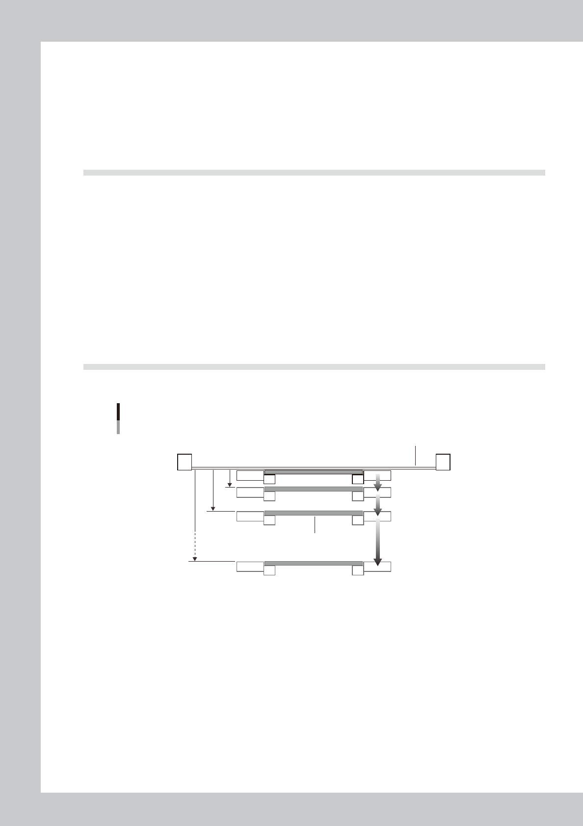
3.6 Detach pattern
On the [Print] – [Squeegee] tab, press the [Detail Setting] and set the parameters on the [Detach Pattern] tab.
Board separation setting
Board
Mask
Distance from printing
height (0.01mm steps)
[0.01∼7.00mm]
Board separation speed
(0.01mm/s steps)
[0.01∼20.0mm/s]
63E05-L3-00
3.6.1 Board separation speed
n
Function
This parameter sets a speed during the board separation.
n
Setting range and initial value
This parameter can be set in a range of 0.001 to 20.000mm/sec.
The initial value is 3.000mm/sec.
n
Setting procedures
Set this parameter while carefully checking the solder shape and the solder remaining at the mask apertures during the
printing.
If this speed is too fast, solder may remain at the mask apertures. Conversely, if this speed is too slow, a solder
entanglement or spread may occur in the printed solder.