YSP_Users_E.pdf - 第257页
A-6 A Appendix 2. Compatible masks 2.1 Mask size and mask stopper pin position T he mask stopper pin position must be changed according to the mask frame size to be used as shown belo w . One screw-type mask stopper pin …
A-5
A
Appendix
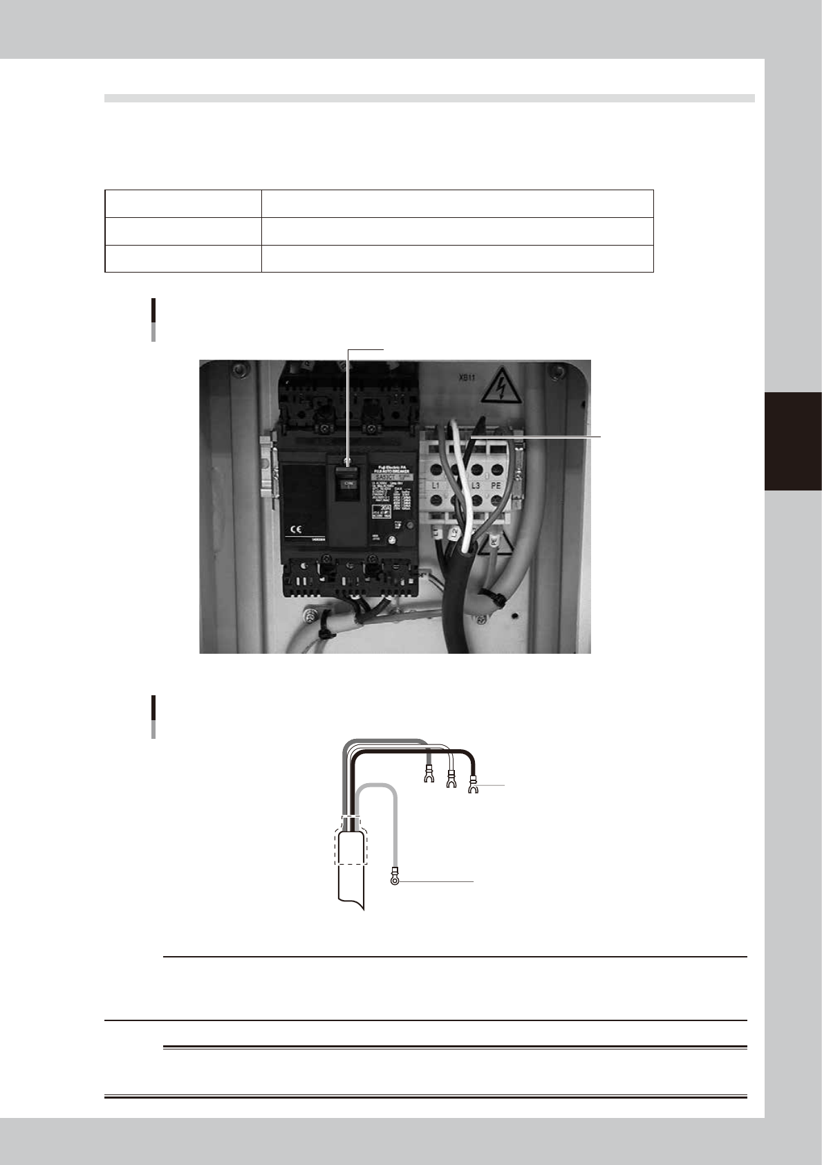
1.3 Power connection terminals
The power connection terminals are located behind the lower right panel on the front of the machine. Use the
power cable shown in the figure below to connect the power cable leads to the primary terminals L1, L2 and
L3 on the main circuit breaker.
n
Power supply specifications
Power 3-phase AC 200 / 208/ 220 / 240 / 380 / 400 / 416V ±10%
Frequency 50/60Hz
Power capacity 3.0kVA (excluding optional temperature control unit)
Power connection terminals
Power input terminal
(L1, L2, L3, PE)
Main breaker
63008-L3-00
L1
U
L2
V
L3
W
Earth
Green
L=350mm
L=350mm
Ring tongue terminal
Fork tongue terminal (vinyl-insulated)
Power cable example
63009-L3-00
c
CAUTION
Use a power cable with a grade of AWG12 (cross-sectional area of the conductor is 3.5 mm
2
) or more.
Make sure that the power cable connections are correct. If misconnected, the vacuum operation of the suction unit
will be reversed (air blows outward).
w
WARNING
TO AVOID THE RISK OF ELECTRICAL SHOCK, MAKE SURE THAT THE POWER SOURCE IS OFF BEFORE CONNECTING THE
POWER CABLE. ALSO MAKE SURE THAT THE GROUND CABLE IS SECURELY CONNECTED TO THE MACHINE.
A-6
A
Appendix
2. Compatible masks
2.1 Mask size and mask stopper pin position
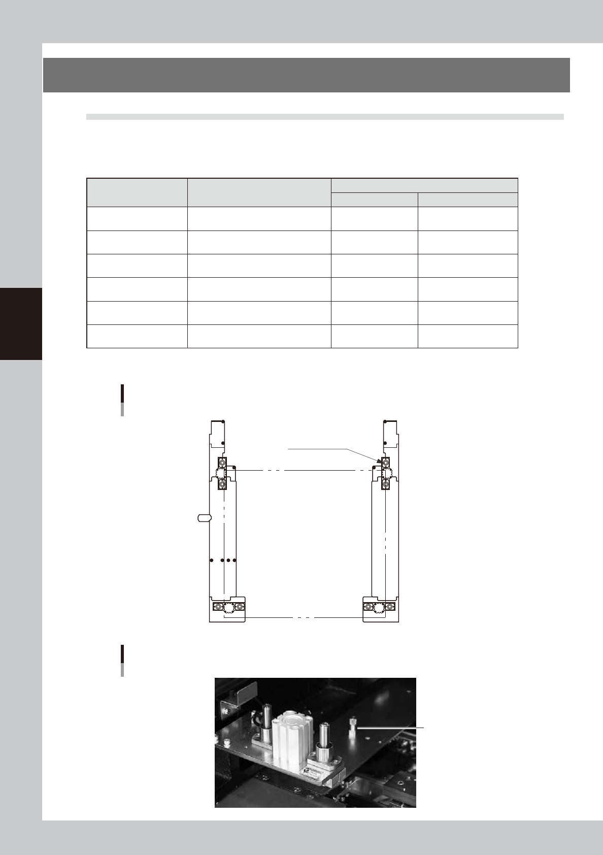
The mask stopper pin position must be changed according to the mask frame size to be used as shown below. One
screw-type mask stopper pin sets the left end position of the mask frame. Screw this stopper pin into one of the "F"
positions when the front conveyor rail is fixed, or one of the "R" positions when the rear conveyor rail is fixed.
n
Mask frame size and stopper pin position
Mask frame size
L (mm) × W(mm)
Applicable board dimensions
L (mm) × W(mm)
Mask frame stopper pin position
L direction W direction
750×750
Board size L50 × W50mm (minimum)
to L510 × W460mm (maximum)
Not used Not used.
750×650
Board size L50 × W50mm (minimum)
to L510 × W460mm (maximum)
Not used 2 (2 locations)
736×736
Board size L50 × W50mm (minimum)
to L510 × W350mm (maximum)
A 1 (2 locations)
650×550
Board size L50 × W50mm (minimum)
to L330 × W250mm (maximum)
B 3 (2 locations)
600×550
Board size L50 × W50mm (minimum)
to L330 × W250mm (maximum)
C Mask adaptor (option)*
550×650
Board size L50 × W50mm (minimum)
to L330 × W250mm (maximum)
D Mask adaptor (option)*
*See "5.1 Using the mask adaptor" in chapter 3 for the mask adaptor (option).
TIP : Store the pins that are not in use.
1
2
1
2
3
A BCD
3
Mask frame size and stopper pin position
Mask frame L
Mask clamp
Mask frame W
63011-L3-10
Mask stopper pin
Mask stopper pin
63012-L3-00
A-7
A
Appendix
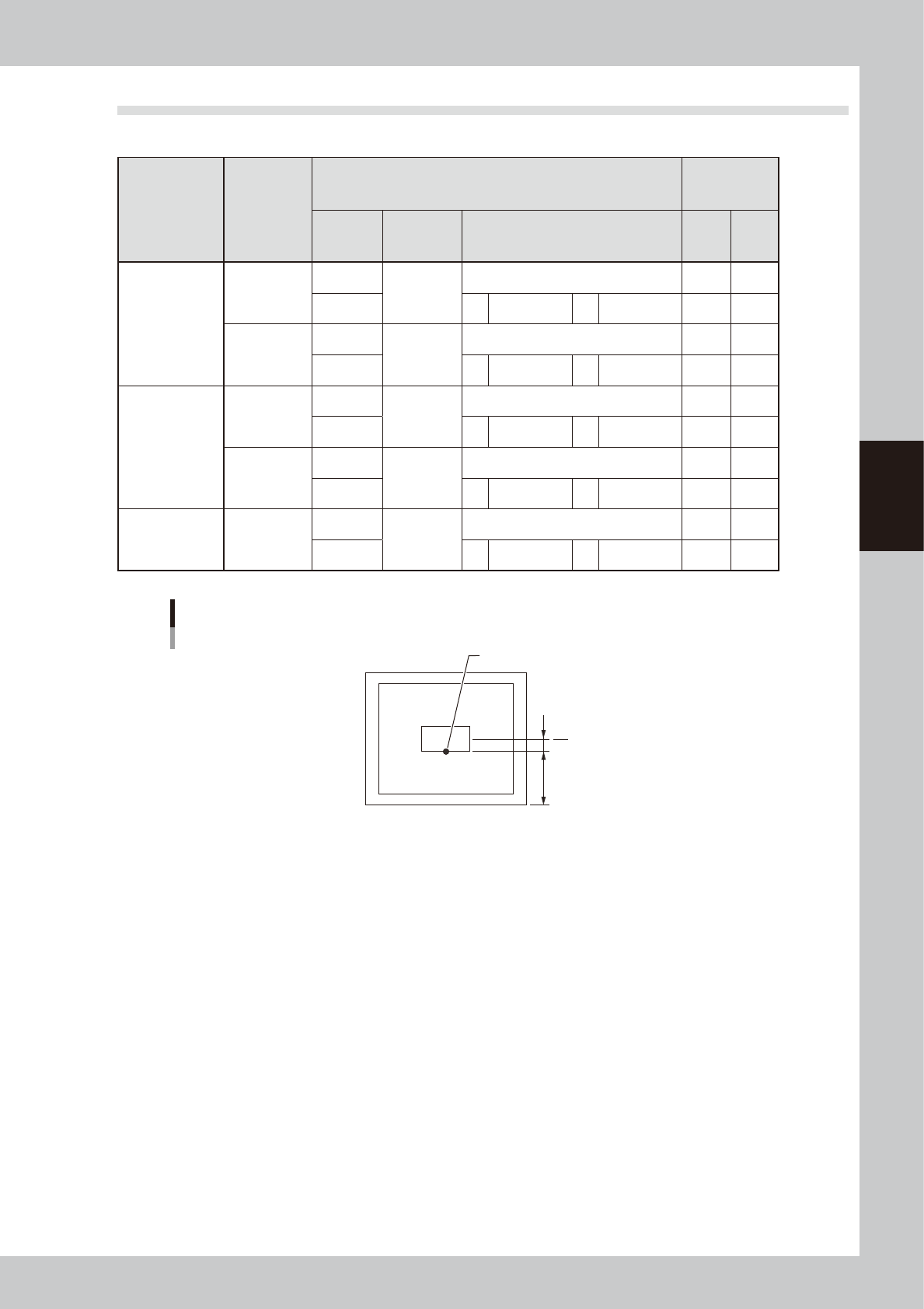
2.2 Mask frame dimensions and mask standard position
n
Mask frame dimensions and mask standard position
Specifications
Applicable
mask frame
size (mm)
Mask standard position
Standard
position
offset
Setting X direction
Y direction
A: From outside of mask frame (mm)
B: From center of mask (mm)
X Y
YSP
L736×W736
Center
Center
Center 0 0
Front A 138 B 230 0 0
L650×W550
Center
Center
Center 0 0
Front A 150 B 125 0 0
Panasonic
L600×W550
Center
Center
Center 0 0
Front A 150 B 125 0 0
L550×W650
Center
Center
Center 0 0
Front A 200 B 125 0 0
Minami Kogaku L750×W650
Center
Center
Center 0 0
Front A 150 B 175 0 0
Mask standard position is “Front”.
Mask standard position “Front”
Mask center
A
B
Standard position
63013-L3-00