YSP_Users_E.pdf - 第52页
1-10 1 Part names and functions 4. Conveyor unit The YSP uses a 3-stage conveyor unit separated into a board carr y-in conveyor , a clamp unit (board clamp table), and a board carr y-out conveyor . The YSP equipped with …
1-9
1
Part names and functions
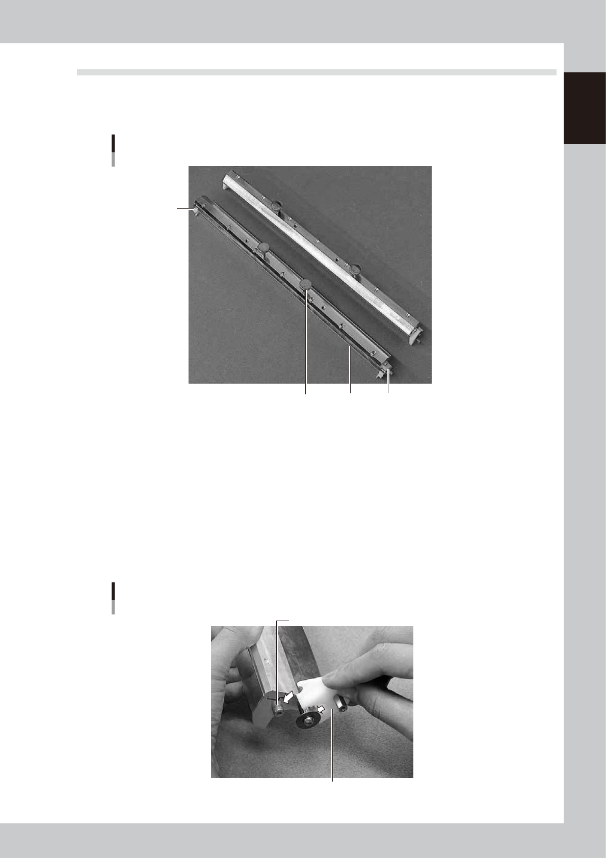
3.3 Double squeegee (option)
Standard machine uses a double squeegee with urethane scrapers or metal scrapers. This double squeegee can
be easily attached or detached from the squeegee holder by using the mount knobs. Double squeegees with a
length of 250mm, 300mm, 350mm, 400mm, 440mm or 530mm are supplied according to your order.
Double squeegee
1
2
3
3
63110-L3-00
1. Scraper
Prints solder patterns on a board while uniformly scraping solder paste placed on the mask. Squeegee scrapers are made
of urethane or metal.
2. Mount knob
Tighten these mount knobs to install the squeegee on the squeegee holder. The squeegee with the narrower mount knob
spacing is should be installed at the front.
3. Side plate
Prevents solder paste on the mask from spreading beyond the squeegee width.
When using metal squeegees, fully insert the side plate onto the guide pin while aligning the side plate notch with the
guide pin, and tighten the thumbscrew to secure the side plate. (Fit the side plates onto both sides of the squeegee.)
Side plate for double squeegee
Side plate
Guide pin
63111-L3-00
1-10
1
Part names and functions
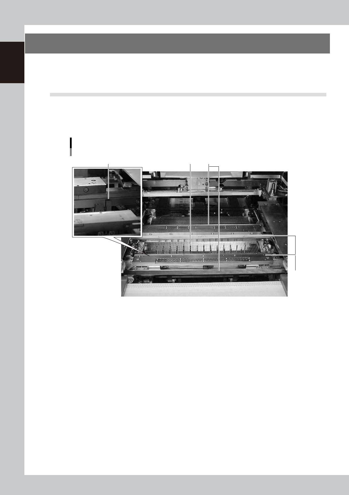
4. Conveyor unit
The YSP uses a 3-stage conveyor unit separated into a board carry-in conveyor, a clamp unit (board clamp
table), and a board carry-out conveyor. The YSP equipped with an optional extended exit conveyor allows a
visual check of printed solder paste at the exit of the conveyor.
4.1 Board clamp unit (board clamp table)
The board clamp table secures a board in the printing position. During recognition or position teaching by the
vision camera, this table moves along the servo-controlled Y-axis (perpendicular to board transport direction).
This table also rotates slightly in the R direction by controlling two X axes. The conveyor rail width is
automatically adjusted according to the board width (Board Size Y).
Board clamp unit
(board clamp table)
21 3
4
63113-L3-00
1. Main stopper
When a board is carried in on the conveyor, the main stopper stops the board at the printing position. The main stopper
is automatically positioned by servo control according to the board length (Board Size X).
2. Push-up plate
The push-up plate moves up by servo control to clamp the board from the bottom. This push-up plate has pin insertion
holes arranged in a matrix, into which matrix pins can be inserted to support the board. (Board support jigs are optional.)
3. Flap
Presses on the board edge from the top to correct the board curvature. These flaps are automatically actuated when the
board is clamped in printing position.
4. Edge clamp
Secures the board in printing position by pushing laterally on the board edge.
1-11
1
Part names and functions
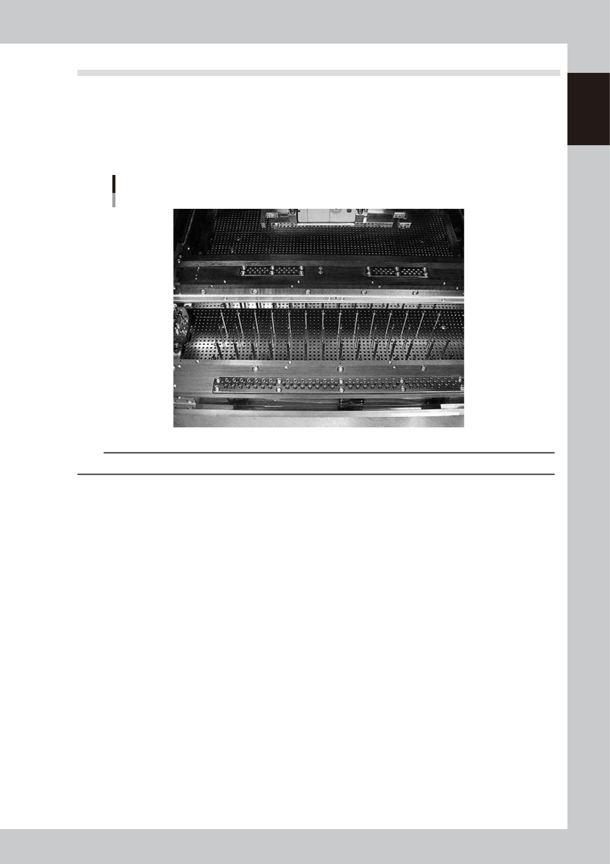
4.2 Board support
Matrix pins are provided to support the board at the printing position by pushing it from the bottom. (Note that
board support jigs are optional.)
l
Matrix pins
For machines with matrix pin specifications, matrix pins into the holes in the push-up plate (matrix plate) in positions
that match the board.
Matrix pins
Matrix plate
63115-L3-00
TIP
The matrix pin arrangement can be registered for each board type. (See "3. Matrix pin arrangement" in Chapter 6.)