YSP_Users_E.pdf - 第146页
4-43 4 Creating and setting the data 1 L oad a board on the conve yor . 1. Press the [Setup] button and select the [Setup] tab. 2. Press the [Conveyor In] button and follow the message on the screen to load the board. 2 …
4-42
4
Creating and setting the data
8. Graphic alignment
When finished creating board data and necessary mark data, you should check to see whether the mask
apertures are aligned with the land patterns on the board, and correct any offsets (positional shifts) as
needed.
n
NOTE
When fiducial marks on the board and mask frame are used, their positions are automatically aligned by vision
recognition, so you can omit "graphic alignment". However, when the fiducial mark positions were defined by
teaching or when the mask aperture shapes are not identical with the land pattern shapes, then position alignment
may not be accurate if only using vision recognition. In those cases, the graphic alignment function allows you to
make position alignment easily and accurately.
l
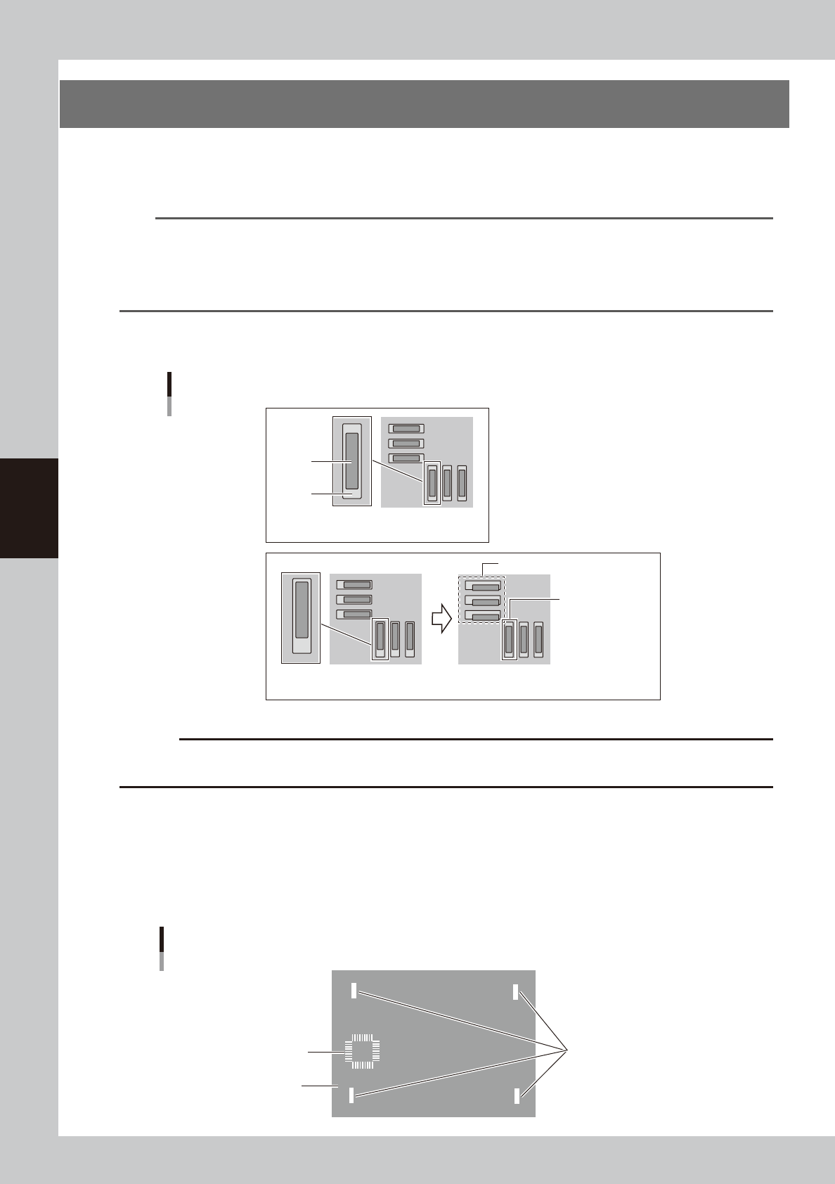
Coordinates used for graphic alignment
For graphic alignment, select the coordinates where the center of the pad meets the center of the solder.
Select the mask hole and the pad
The center of the pad doesn't meet
the center of the solder
Center aligned place
Deviated place
Aligning a place to the center may effect to align
the other place wrong.
The center of the pad meets
the center of the solder
Solder
Pad
OK
NG
63436-L3-00
c
CAUTION
If the coordinates where the center of the pad doesn't meet the center of the solder are selected, the graphic
alignment results wrong offset.
1. If the center deviation and rotational deviation exist, specify four diagonal points as shown below.
2. If you want to make alignments at a particular point other than the above four diagonal points, then specify only that
one point after adjusting the rotational deviation of the entire board by specifying the two diagonal points. If two
particular points are specified in this case, the rotational component that has already been adjusted will change, so use
caution.
The coordinates to be specified for graphic alignment should be measured in advance, or if the coordinate data (design
data) is available, make a note of the coordinates in advance.
Specify four corners diagonally
(for correction center and
rotational deviation.)
Alignment coordinates number
2
3
4
1
5
The specified position to be aligned
(Specify only one point)
Specified coordinates for graphic alignment
63428-L3-10
4-43
4
Creating and setting the data
1
Load a board on the conveyor.
1. Press the [Setup] button and select the [Setup] tab.
2. Press the [Conveyor In] button and follow the message on the screen to load the board.
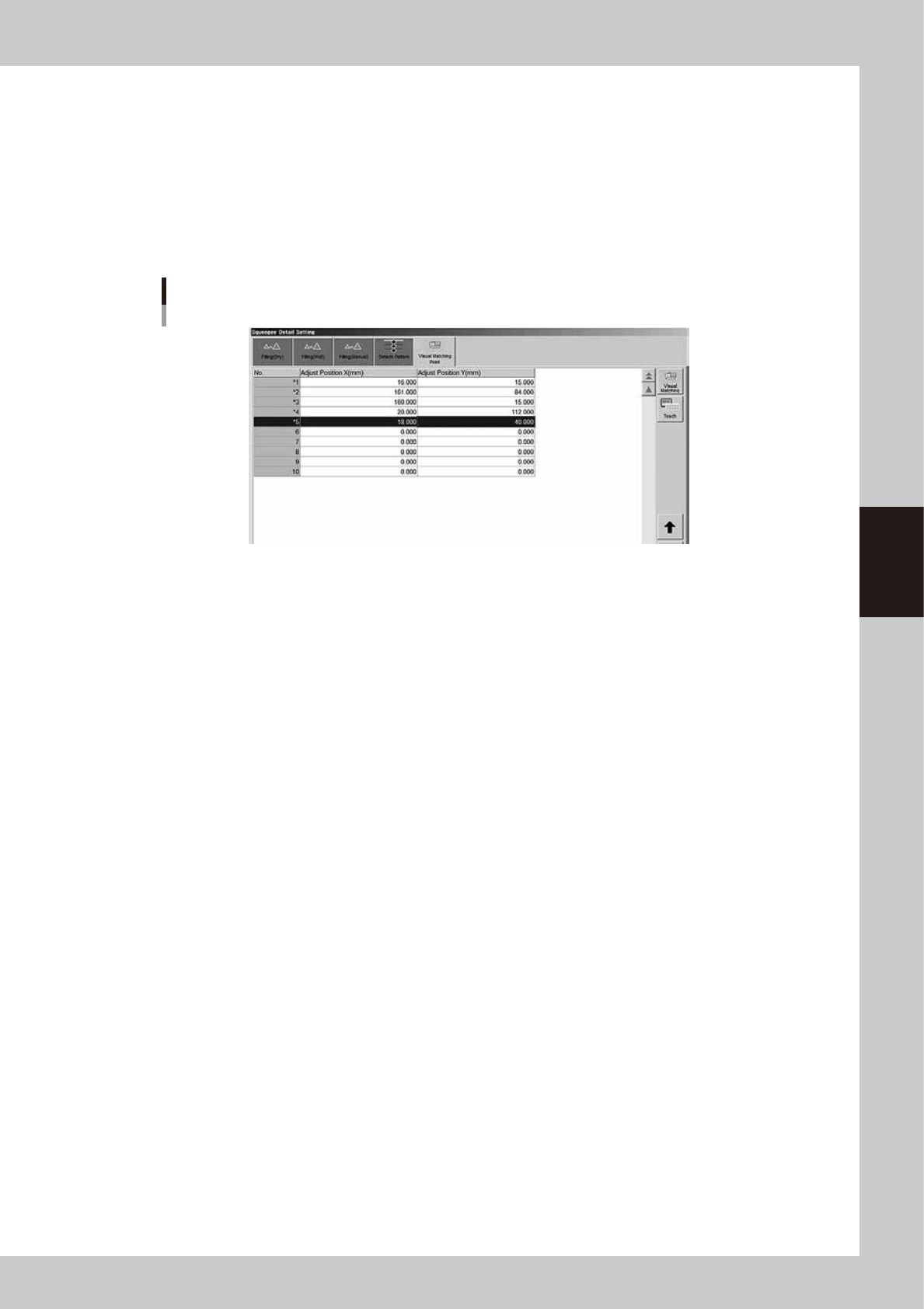
2
Temporarily enter the coordinates used for graphic alignment.
1. Press the [Print] button, open the [Squeegee] tab, and press the [Detail Setting] button.
2. Open the [Visual Matching Point] tab.
3. In the ""Adjust Position X" and "Adjust Position Y" fields, enter the coordinates that have been
measured in advance.
Temporarily entering the coordinates for graphic alignment
64441-L3-10
4-44
4
Creating and setting the data
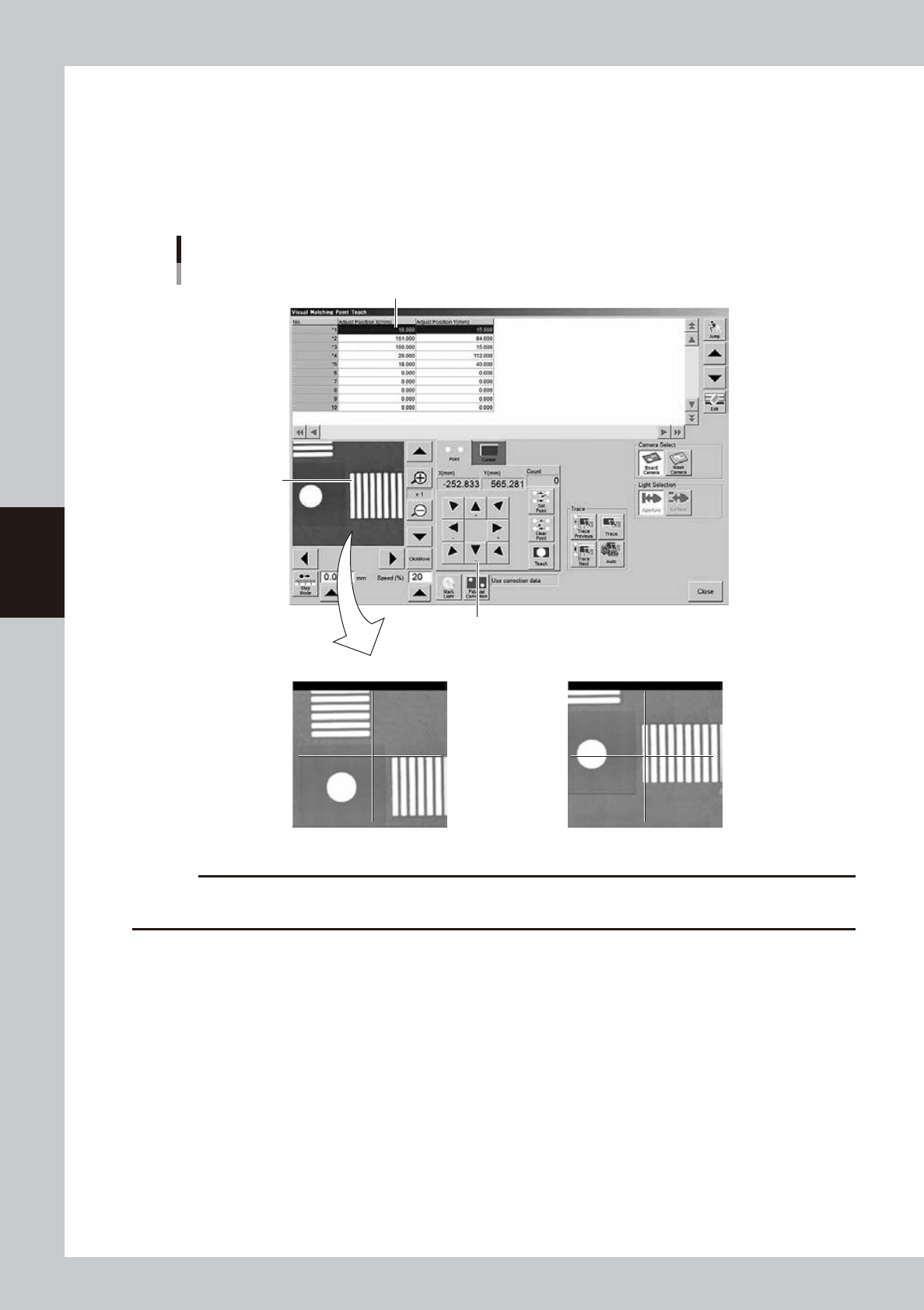
3
Teach the coordinates for graphic alignment.
1. Press the [Teach] button to open the teach window for graphic alignment.
2. Position the cursor on the first coordinates and press the [Trace] button.
3. Using the arrow keys, align the target coordinates (pad) with the center.
4. Press the [Teach] button to teach the coordinates.
Use the same method to teach the second point.
Teach window for graphic alignment
Arrow keys
NG OK
Pad to be aligned
Alignment coordinates
64442-L3-10
c
CAUTION
Alignment coordinates must be aligned on the center of the pad. If the coordinates are aligned at the edge of the
figure, it may cause wrong alignment.