YSP_Users_E.pdf - 第222页
7-13 7 Replacing the consumable parts 5. Suction-blower unit The suction-blower unit is always operated even when the machine is in emergency stop. It is therefore necessar y to clean and replace the filter and replace t…
7-12
7
Replacing the consumable parts
4.3 Long-term storage tasks
If the solvent pump is not used for extended periods (about 6 months or more), then it may dry out internally
and cause operating defects. The solvent path within the pump must be blocked to prevent this from happening.
The path blocking procedure is described below.
n
Blocking the solvent path
1
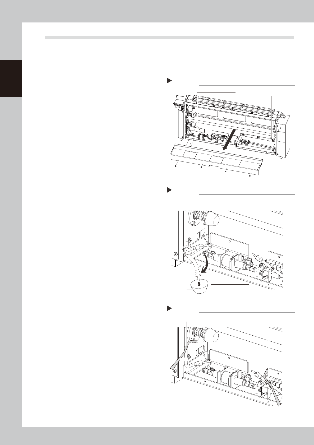
Remove the cleaner cover.
1. Loosen the two screws (enclosed by a
dashed line circle in the figure on the
right) clamping the rear side of the
cleaner cover. (No need to remove
them)
2. Next remove the screws at 4 locations on
the near side (see drawing).
3. Raise the cover upward and then pull
toward you to remove it.
63720-L3-00
2
Remove the joints.
Remove the joints from two locations, one
on the head side and the other on the tank
side from the shut-off valve joint. Use caution
because alcohol remaining in the hose will
come out when the joint on the head side is
removed.
1. Remove the head side joint in the bent
state as shown by the dashed line in the
figure on the right.
2. Prepare a container, free the bent
location and let the alcohol drain into
the container.
3. Remove the tank side joint and then
quickly point it upward to let the alcohol
in the hose return back to the tank.
63721-L3-00
3
Mark the hoses you removed.
Mark the two hose sections you removed in
step 2 by winding yellow ribbon or a similar
item around them.
63722-L3-00
4
Reattach the cleaner cover.
Reinstall the cleaner cover in the reverse of
the procedure that you removed it in step 1.
Place a ribbon on the outer side of the
cover so that others will know that the joints
were removed.
n
Resetting operation
Connect the hoses in the reverse of the "Blocking the
solvent path" procedure and refill with solvent by
referring to 4.2 "Refilling the solvent". When finished
refilling, operate the solvent pump to make sure it
operates correctly.
Removing the cleaner cover
Step 1
First loosen these two screws.
Removing the joints
Step 2
Joint (to head)
Shut-off valve joint
Container
Joint (to tank)
Hose markings
Step 3
Marking (yellow ribbon, etc.)
Marking
As seen from outside the cover
7-13
7
Replacing the consumable parts
5. Suction-blower unit
The suction-blower unit is always operated even when the machine is in emergency stop. It is therefore
necessary to clean and replace the filter and replace the blower hose periodically.
5.1 Replacing the filter
To clean and replace the filter, follow the steps below.
e
1
Press the emergency stop button.
2
Open the lower cover on the rear
of the machine.
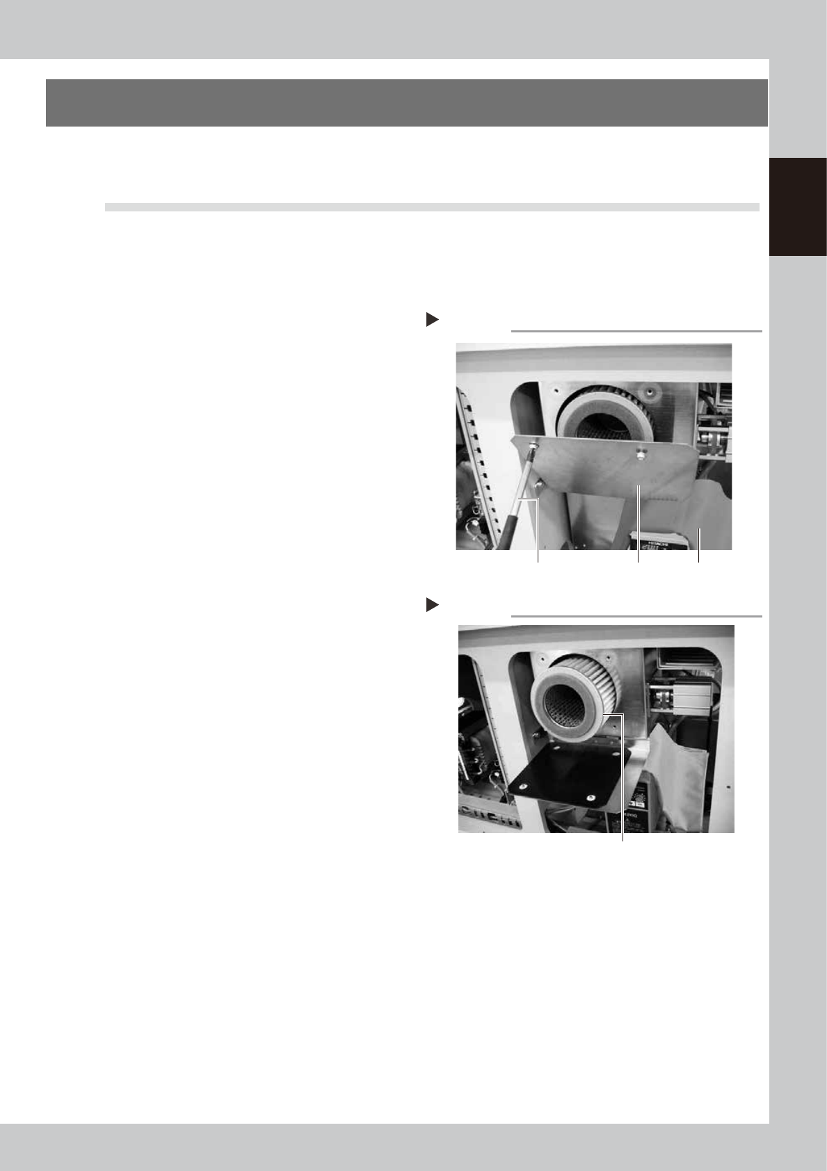
3
Protect the inverter main unit.
Cover the inverter main unit with a cloth rag
to prevent entry of dust.
63021-L3-00
4
Remove the cover.
Remove two screws from the upper portion
with a Phillips screwdriver. The cover is then
opened like it falls down.
5
Take out the filter and clean it.
Take out the ring filter and blow the air from
the inside of the filter with an air gun.
63022-L3-00
6
Return the filter to its original
position.
Insert the filter to its original position and
close the cover.
Removing the cover
Step 3, 4
Phillips screwdriver Cloth ragCover
Taking out the filter
Step 5
Filter
7-14
7
Replacing the consumable parts
5.2 Replacing the blower hose
ITo replace the blower hose, follow the steps below.
e
1
Press the emergency stop button.
2
Open the rear cover of the
machine.
3
Remove the blower hose from the
blower.
1. Move the board clamp table on the
Y-axis to the front side of the machine.
2. Remove the hose band with a flat-blade
screwdriver and remove the blower hose
from the vacuum pipe.
3. Loosen the mounting bolts on the hose
clamps (2 bolts on each clamp) with an
Allen wrench (4mm).
4
Open the front cover of the
machine.
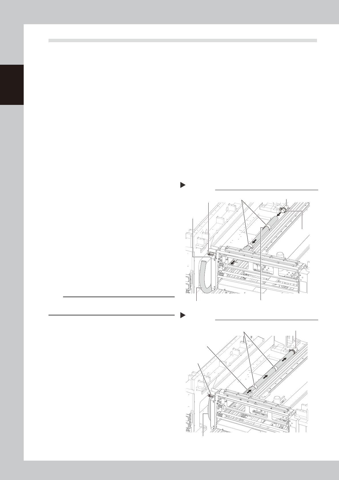
5
Remove the blower hose from the
cleaner.
1. Pull the cleaner head to the front of the
machine.
2. Loosen the hose band with a flat-blade
screwdriver and remove the blower hose
from the joint.
3. Pull out the blower hose.
63723-L3-00
6
Insert a new blower hose from the
cleaner side.
1. Insert the new blower hose and pass it
through the hose clamps.
n
NOTE
Insert the blower hose so that it smoothly bends
upward.
2. Connect the blower hose to the joint and
tighten the hose band with the flat-blade
screwdriver to clamp the hose.
7
Temporarily connect the blower
hose on the blower to the vacuum
pipe.
1. Move the board clamp table on the
Y-axis to the front side.
2. Temporarily connect the blower hose to
the vacuum pipe.
63724-L3-00
8
Check the blower hose position
while viewing from the cleaner
side.
Move the cleaner head in the Y direction
and check that the blower hose is
positioned straight on the hose guide.
Removing the blower hose
Step 5
Hose band
Hose band
Hose clamp
Mounting bolt (2 bolts on each clamp)
Joint
Vacuum pipe
Blower hose
Inserting the blower hose
Step 6,7
Hose guide
Blower hose
Vacuum pipe
Hose clamp
Joint