YSP_Users_E.pdf - 第43页
1-1 1 Part names and functions 1. YSP main unit A standard machine has the following configurations after installation. Names and functions of major parts of the main unit are described on the subsequent pages. YSP main …

Chapter 1 Part names and functions
This chapter explains YSP major part names and functions. Make sure that you understand the location and function of each
part before attempting machine operation.
Contents
1. YSP main unit 1-1
2. Operation panels and data input units 1-4
2.1 Operation panel buttons 1-5
2.2 Keyboard and mouse 1-6
2.3 Liquid crystal touch screen (option) 1-6
3. Printing section 1-7
3.1 Squeegee head and printing table 1-7
3.2 3S squeegee 1-8
3.3 Double squeegee (option) 1-9
4. Conveyor unit 1-10
4.1 Board clamp unit (board clamp table) 1-10
4.2 Board support 1-11
4.3 Board carry-in and carry-out conveyors 1-15
4.4 Extended exit conveyor (option) 1-15
4.4.1 MANUAL mode 1-16
4.4.2 AUTO mode 1-17
5. Cleaning unit 1-18
5.1 Cleaning unit 1-18
5.2 Suction unit 1-19
6. Camera unit 1-20
7. Servo-controlled axes 1-21
1-1
1
Part names and functions
1. YSP main unit
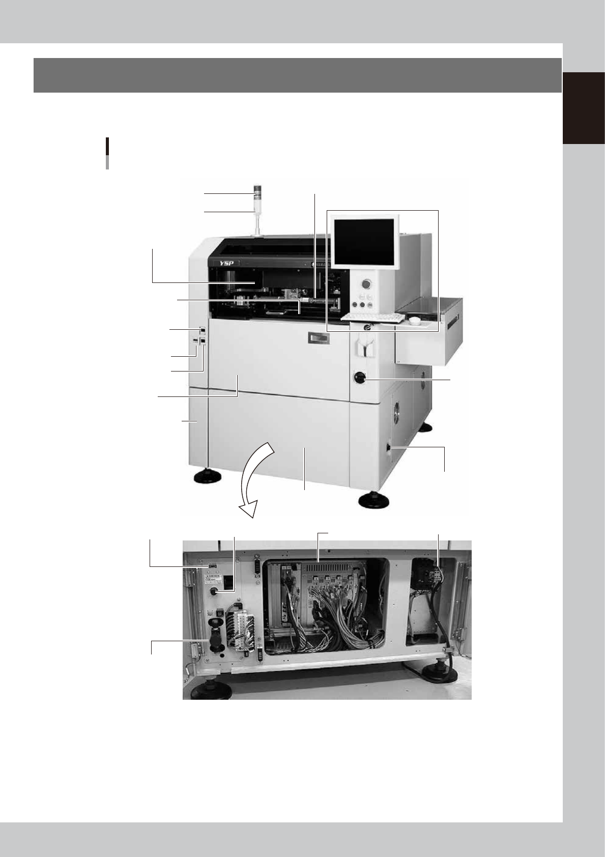
A standard machine has the following configurations after installation. Names and functions of major parts
of the main unit are described on the subsequent pages.
YSP main unit
Front view
Signal light
Operation panel and data input unit
Power switch
Upper door (safety cover)
Edge clamp
pressure gauge
Cleaner vaccum
pressure gauge
Pressure gauge
Front lower panel
Conveyor unit
(below printing table)
Air supply/exhaust switch
Controller
Printing section
(Squeegee head, printing table)
I/O signal connector
(both left and right sides)
Buzzer
Pressure regulator (for air supply)USB port
Power connection terminals
Front panel
Front lower left panel
63101-L3-10
1-2
1
Part names and functions
Signal light and buzzer
Indicates current operating conditions of the machine with a green, yellow and red light explained below.
n
Signal light
Signal light/buzzer Machine status
All lamps are off Machine is in stop or reset status.
Red
Machine is in emergency stop. (Emergency stop button on the machine or safety switch
was activated.)
Yellow Error (recognition error, board clamp error, etc.) or interlock has occurred.
Green
Machine is in automatic operation, rolling operation, alignment operation, or warm-up
operation.
Buzzer
Buzzer sounds if an error or abnormal operation occurs. Volume can be adjusted by
turning right or left.
Upper door (safety cover)
This cover must be kept closed during operation. If opened, emergency stop is triggered.
Pressure gauge, pressure regulator, air supply/exhaust switch
Indicates and adjusts the air pressure supplied to the machine. See Appendix 1.1, "Air regulator unit", for more details.
Printing section
Consists of a printing table and a squeegee head. See "3. Printing section" later in this chapter for more details.
Front panel
This panel contains the camera unit and conveyor unit. See "4. Conveyor unit" and "6. Camera unit" later in this chapter
for more details.
Cleaning unit and solvent tank (behind front cover)
The cleaning unit uses a gauze roll to wipe away solder adhering to the mask apertures and solder coming out of the
backside of the mask while vacuuming. See "5. Cleaning unit" later in this chapter for more details.
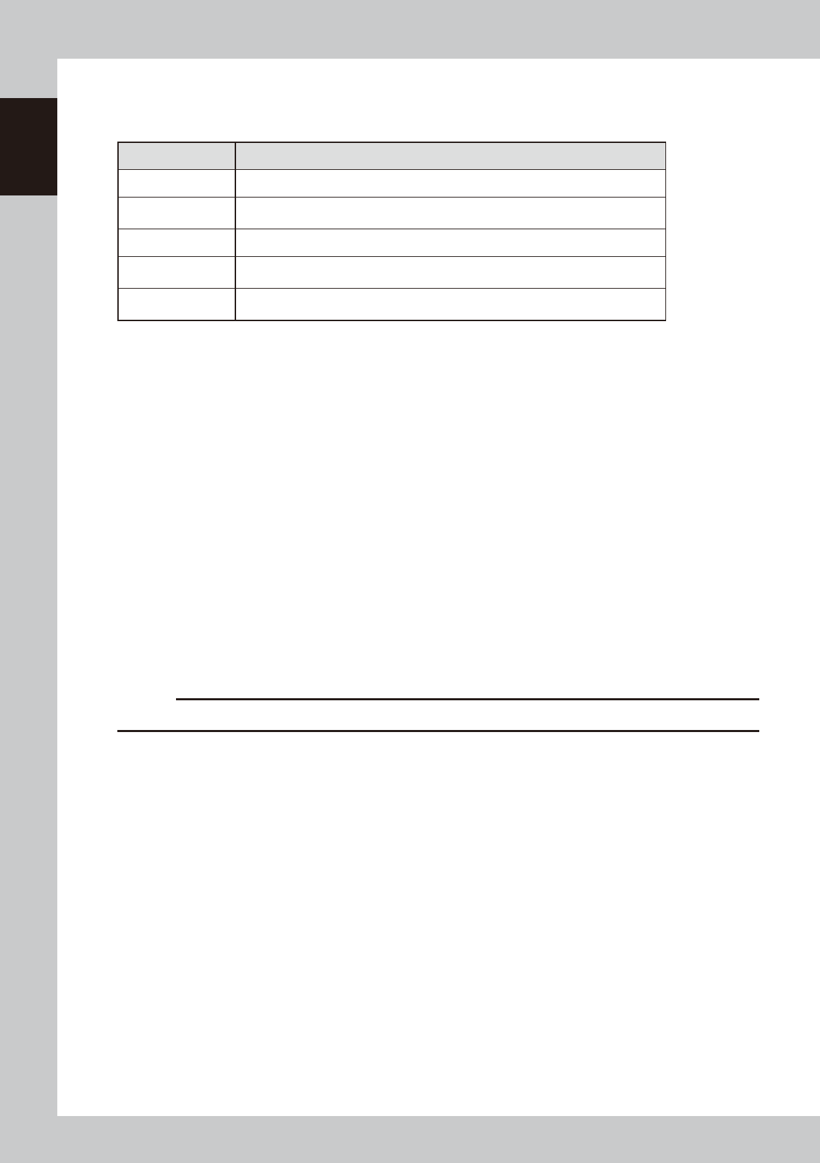
Front lower panel
Installed behind this panel are the system mother board, power supply board, servo control board, vision board, and
power connection terminal block.
Power switch
Turns the power to the machine on and off. The power is on when turned to the right.
c
CAUTION
Wait about 2 seconds before turning the power switch back on after having turned it off.
USB port (behind front lower left panel)
Connect to this port when using a USB memory device to back up board data stored in the machine. Always close this
media access door before operating a USB memory device.
I/O signal connectors
These connectors are located on the left and right panels of the machine and are used to connect to upstream and
downstream machines. See Appendix 1.2, "Connection between machines", for more details.
Conveyor unit
A three-stage (board carry-in, clamp, carry-out) conveyor is installed under the printing table. See "4. Conveyor unit"
later in this chapter for more details.