YSP_Users_E.pdf - 第87页
3-7 3 Daily operation 5. Setting up the mask and squeegee This section explains procedures for clamping the mask (stencil) you have prepared on the printing table and installing the squeegee onto the squeegee head. e 1 P…
3-6
3
Daily operation
e
4
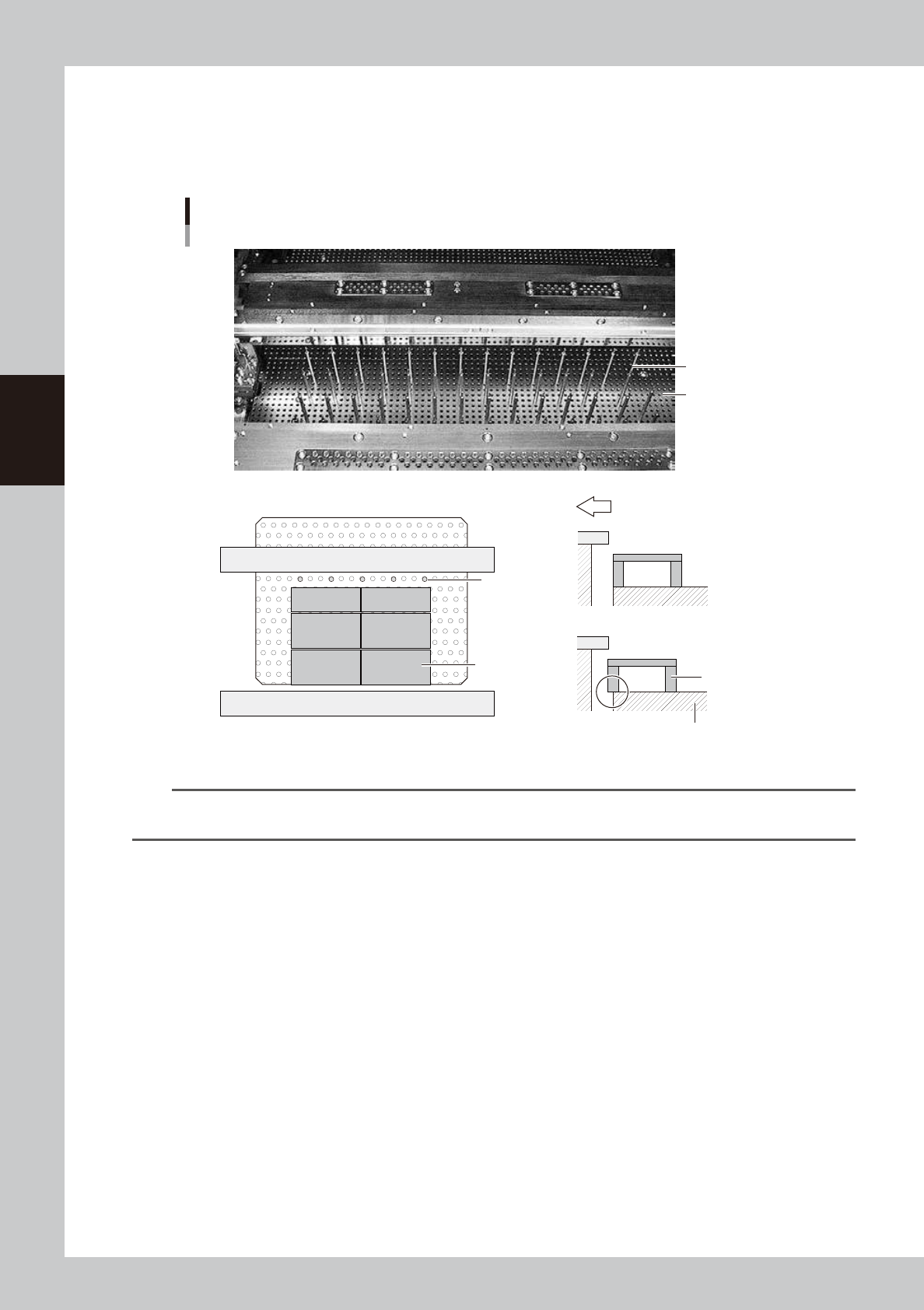
Set the matrix pins (or board support jigs).
Press the emergency stop button and open the upper door. Arrange the matrix pins on the push-up
plate according to the width of a production board. When using optional board support jigs, they can
also be used together with the matrix pins.
OK
NG
Arranging the matrix pins
Matrix pins
(When board support jigs and matrix pins are used together)
Board support jig
Board support jig
Machine front side
Matrix plate
Matrix pins
Matrix plate
63302-L3-10
n
NOTE
When the matrix pin arrangement has been input by pressing the [Backup Pin Pos.] button on the [Print]-[Board] tab
screen, this is convenient to arrange the matrix pins. (For more details, see “3. Back pin arrangement” in Chapter 6.)
5
Cancel emergency stop.
Close the upper door, release the emergency stop button and press the [READY] button on the
operation panel.
6
Press the [Convey In] button to load a board.
Load a board by following the message that appears on the screen, and the board will be
automatically clamped in printing position.
e
7
Check that the board is uniformly clamped on the conveyor.
After pressing the emergency stop button, lightly press and tap on the board by hand to check that
there is no warp or play in the board.
3-7
3
Daily operation
5. Setting up the mask and squeegee
This section explains procedures for clamping the mask (stencil) you have prepared on the printing table and
installing the squeegee onto the squeegee head.
e
1
Press the emergency stop button and open the upper door.
2
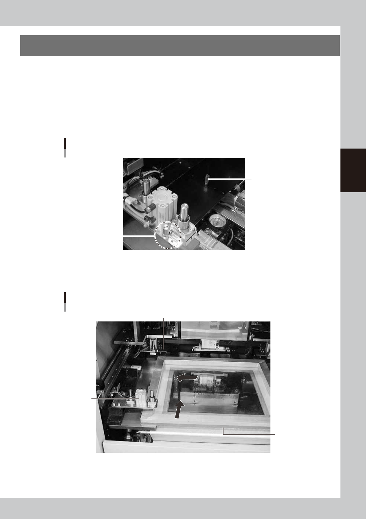
Check or change the mask stopper pin position.
If you are using a mask whose frame size is different from the mask previously used, you must change
the mask stopper pin position on the left side of the printing table (W and L). Screw the mask stopper pin
into the correct hole by referring to the diagram affixed to the inner side of the upper door or Appendix
2.1, "Mask size and mask stopper pin position" in this manual.)
Mask stopper pin
L direction
Mask stopper pin
Put it here when do not
use the mask stopper pin.
63303-L3-10
3
Bring the mask in contact with the stopper.
While keeping the mask frame horizontal, fully insert it in against the left stopper pins along the rear
stopper pins on the printing table.
Mask frame setup
Mask clamp
Mask clamp (adaptor)
Mask frame
63304-L3-00
3-8
3
Daily operation
4
Clamp the mask.
With the mask kept in contact with the left corner on the rear of the printing table, turn the mask clamp
switch located on the right of the machine clockwise to clamp the mask.
c
CAUTION
Be careful not to pinch or crush fingers between the mask frame and mask clamps.
5
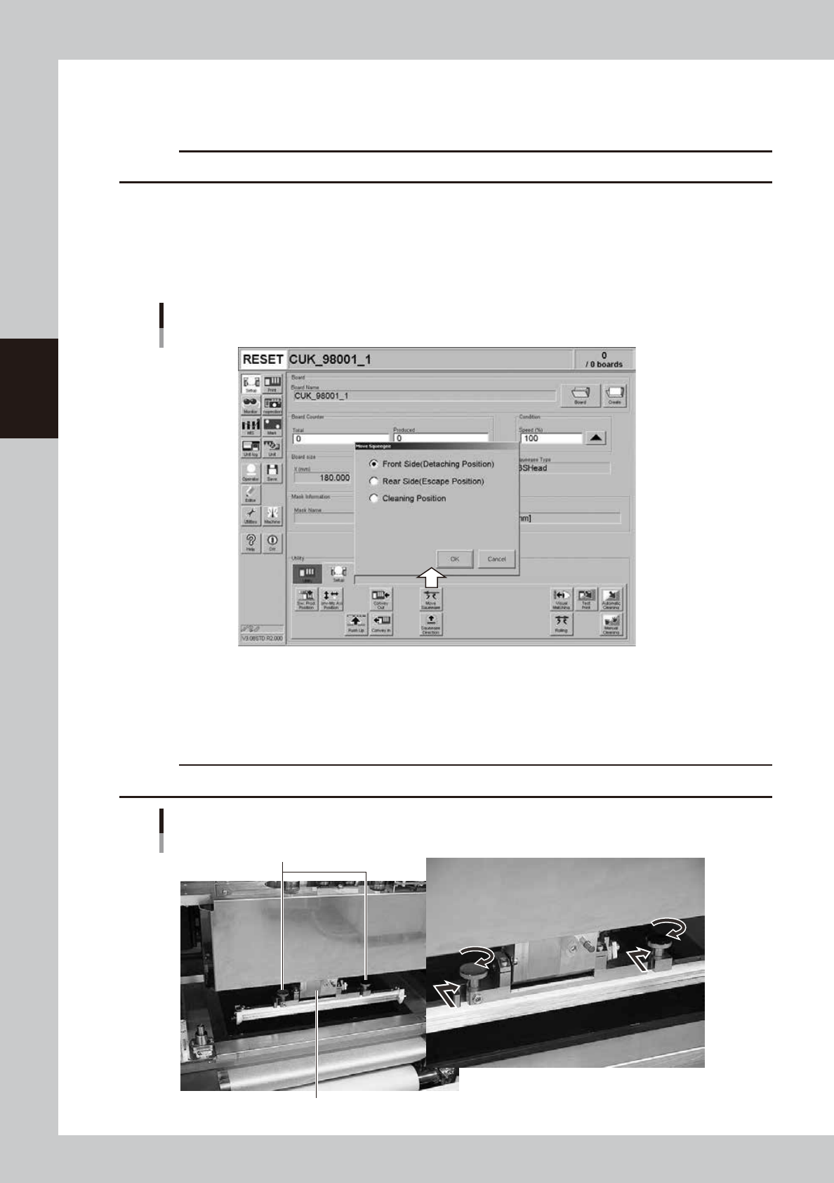
Move the squeegee head to the attach/detach position.
1. After closing the upper door and canceling emergency stop, press the [Move Squeegee] button.
The squeegee position dialog box appears.
2. Select the "Front Side" position (attach/detach position) and press the [OK] button.
The squeegee head moves to the front side (towards you).
Squeegee position dialog box
64309-L3-00
e
6
Press the emergency stop button and open the upper door.
7
Install the squeegee to the squeegee head.
Fit the mount knobs into squeegee head holder and tighten them as below.
c
CAUTION
Be sure to use squeegees specified for use with the YSP.
Attaching the 3S squeegee
Mount knobs
Squeegee holder
63307-L3-10