YSP_Users_E.pdf - 第186页
6-2 6 Other functions 1.2 T each screen Pressing a [T each] button opens the T each screen as sho wn below . T he function of each button on this screen is described below . T each screen Example of board fiducial 2 3 4 …
6-1
6
Other functions
1. Teach and trace
1.1 [Teach] button
The teaching function is used to teach the machine position such as XY coordinate values using a teaching unit
such as a vision camera. To perform teaching, use the [Teach] button to open the Teach screen. There are five
[Teach] buttons at the following locations. Select a [Teach] button suitable for your purpose.
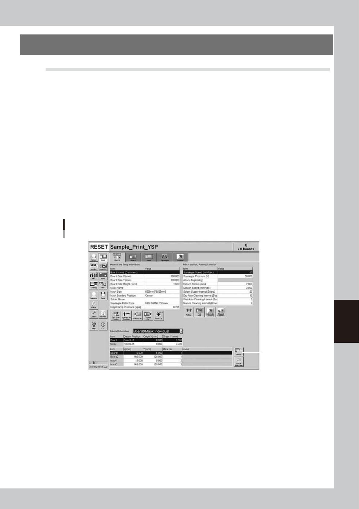
1. [Print] - [Basics] tab:
Press this [Teach] button to perform teaching on the board coordinates.
2. [Print] - [Board] tab:
Press this [Teach] button to perform teaching on the board coordinates.
3. Board inspection coordinate dialog box:
This dialog box appears when the [Detail Condition] button on the [Print] - [Board] tab screen is pressed.
Use the [Teach] button in this dialog box to teach the machine a board inspection position or move the machine to a
specified position.
4. [Print] - [Mask] tab:
Press this [Teach] button to teach the machine the mask coordinates.
5. Mask inspection coordinate dialog box:
This dialog box appears when the [Detail] button on the [Print] - [Mask] tab is pressed. Use the [Teach] button in this
dialog box to teach the machine a mask inspection position or move the machine to a specified position.
[Teach] button
Example of [Basics] tab
[Teach] button
64601-L3-10
6-2
6
Other functions
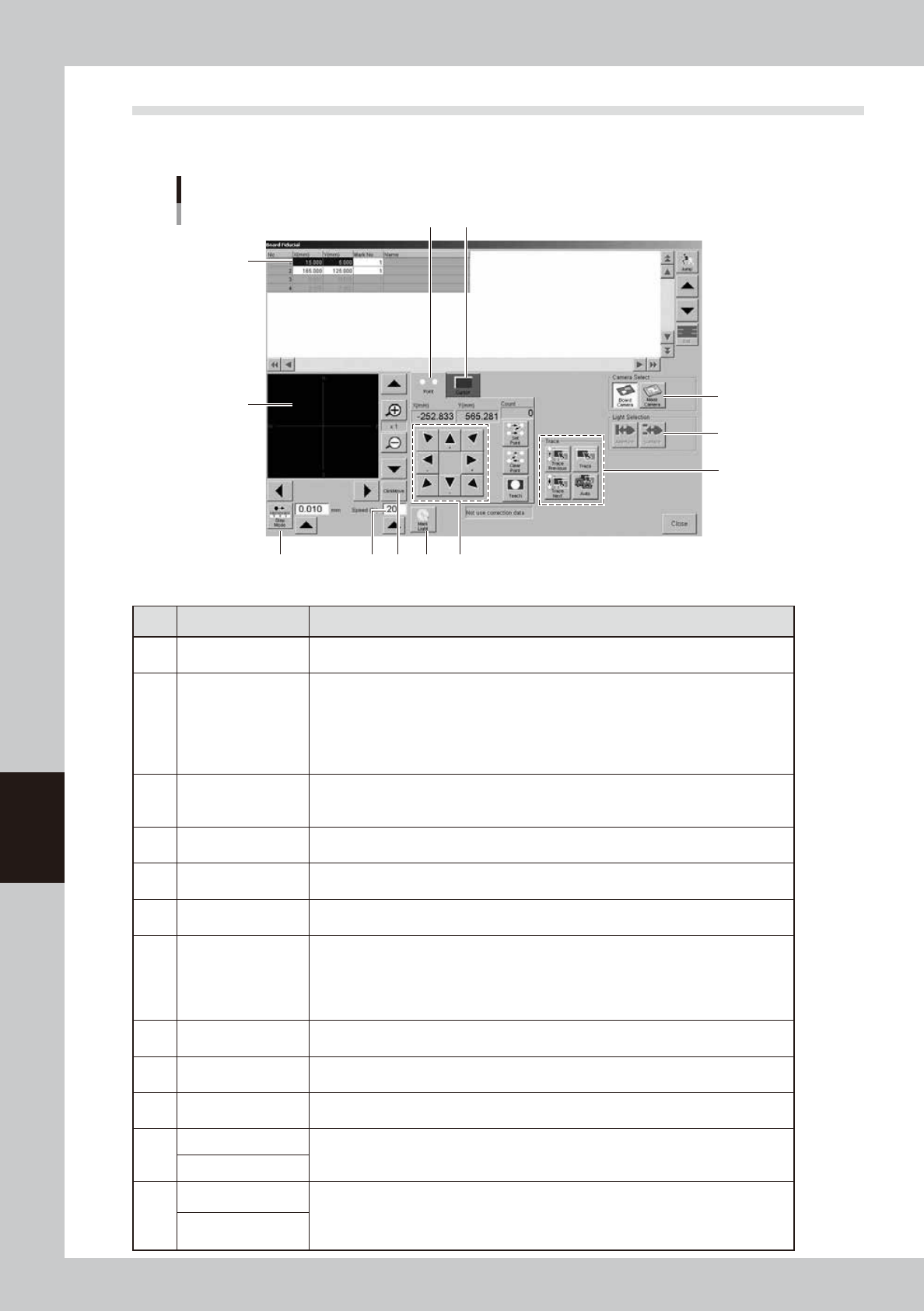
1.2 Teach screen
Pressing a [Teach] button opens the Teach screen as shown below. The function of each button on this screen is
described below.
Teach screen
Example of board fiducial
2
3 4
10
5
6
87 9
12
11
1
64602-L3-00
Item/button name Function
1 Data list
Shows the data to perform teaching.
Items displayed here differ depending on which of the [Teach] buttons is pressed.
2 Vision monitor
Shows an image of the object being viewed by the vision camera during teaching.
The image can be enlarged from 1 to 16 fold by pressing the enlarge [+] button, or
reduced to 1/16 by pressing the reduce [-] button.
The arrow buttons at the right top and bottom of the screen are used to move the image
vertically. The buttons at the bottom left and right of the screen are used to move the
image horizontally.
3 Step Mode
When this button is pressed, you can move the teaching unit in step mode (inching
mode). Select the inching stroke (movement amount) by using the [Up Arrow] button or
entering the desired value in the box.
4 Speed
Select the axis movement speed by using the [Up Arrow] button or entering the desired
speed in the box.
5 [Point] tab
Select the [Point] tab to perform point teaching.
See "1.3 Point teaching" in this chapter for details.
6 [Cursor] tab
Select the [Cursor] tab to perform cursor teaching.
See "1.4 Cursor teaching" in this chapter for details.
7 Click Move
When this button is pressed and the mouse pointer is placed within the vision monitor,
the mouse pointer changes to a cross pointer. Place the cross pointer at the position you
want to teach and press the left mouse button. The camera will move to the teaching
position to display it in the center of the vision monitor. This method makes it easier to
specify the teaching point without using the axis movement buttons.
8 Light
Pressing this button opens the light level adjustment screen. Adjust the light level for the
clearest view of the object on the vision monitor.
9 Axis movement
Moves the teaching unit in the direction of arrow. Keep pressing the arrow button to
make a continuous movement.
10 Trace
Pressing this button moves the teaching unit to the currently selected data position.
See "1.5 Trace" in this chapter.
11
Board Camera
Camera selection buttons. These buttons are used to select the board camera or mask
camera.
Mask Camera
12
Aperture
These buttons can be used when the [Mask Camera] button is selected in the “Camera
Select” area.
Use the [Aperture] button to check the clogging status of the mask apertures. Conversely,
use the [Surface] button to check the solder sticking to the backside of the mask.
Surface
6-3
6
Other functions
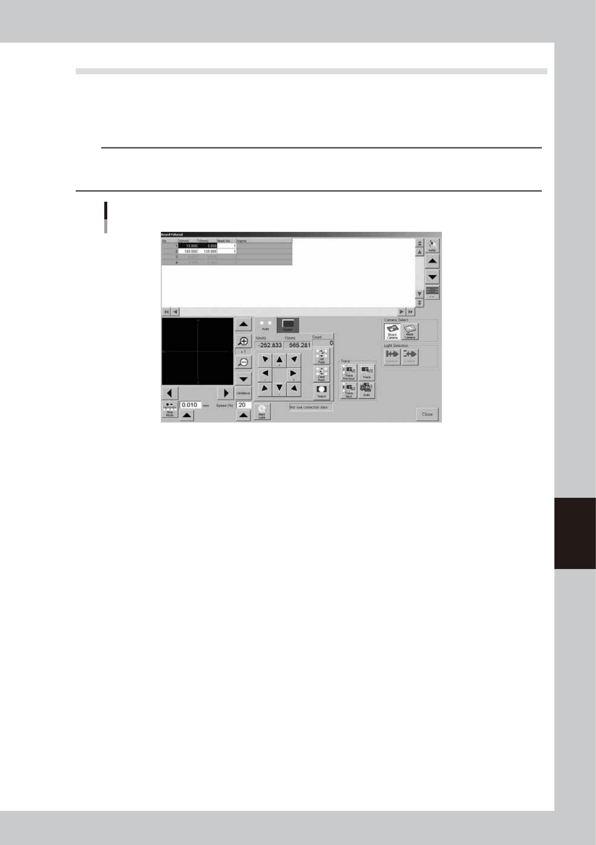
1.3 Point teaching
Point teaching can be performed by "one-point input" or "multi-point input". The "one-point input" allows the
teaching data to be directly entered. The "multi-point input" gives the center coordinates in the multiple
positions that were specified.
1
Press the [Teach] button to open the Teach screen.
TIP
When you perform teaching on a board and the board is not yet clamped on the conveyor, a check dialog box
appears asking you to load a board. Follow the message on the screen to load the board on the conveyor.
When you perform teaching on a mask, clamp the mask on the printing table.
Teach screen
Point teaching
64603-L3-00
2
Check the [Point] tab is opened.
3
Set the speed and operation mode.
Use the [Up Arrow] button or enter the desired speed in the box set the axis movement speed during
teaching. Setting to a lower speed is recommended for safety.
When the [Step Mode] button is pressed, you can move the teaching unit in the inching mode (jog
mode).
4
Follow the message on the screen to load a board on the conveyor.
This step is skipped when a board has already been clamped on the conveyor.
After the board is clamped, the board fiducial mark will be automatically recognized with the vision
camera. (This mark recognition is skipped if not using the fiducial mark function.)
5
Select the data item for which you want to perform teaching.
Line up the cursor with the data line on the upper part of the Teach screen.
6
Move the teaching unit to the target position.
Check safety and stay out of the axis movement range, then use the arrow buttons to move the
teaching unit to the target position. Hold down the arrow button for a continuous movement. The
current XY coordinates are shown on the arrow buttons.