YSP_Users_E.pdf - 第265页
E-3 Printing guide 5 Check the board clamp status. 1. Press the [Convey In] button. Follow the instructions that appear on the operation screen to load a board. 2. When the board is clamped, check the following points. •…
E-2
Printing guide
2. Data and condition setting
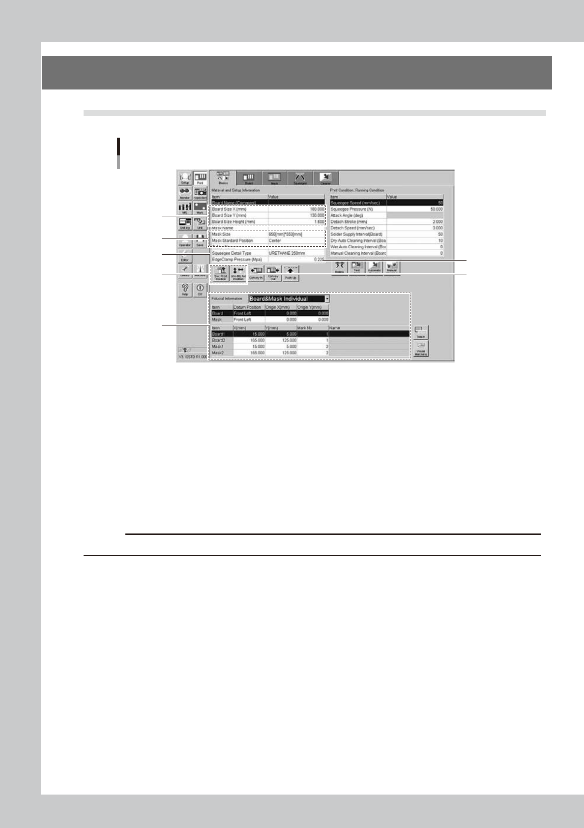
2.1 Material and setup information
Material and setup information
1
2
3
4
6
8
5
64E03-L3-10
1
Enter board size data.
Enter accurate size data (X, Y, height) of the board to be printed.
X : Sets the main stopper position.
Y : Sets the conveyor width.
Height : Sets the backup height.
2
Enter mask information.
1. Select a size of the mask to be used.
2. Select a mask standard position (standard position during the mask processing) (center or front
position).
c
CAUTION
In the YSP, you cannot use the rear position. Always select either the center or front position.
3
Select a squeegee type.
Select a type and size of the squeegee to be used. Each squeegee type has the features described
below.
Urethane squeeze : If the squeegee pressure level is too high, the squeegee is deformed, causing the
solder to be scraped away too much.
Metal squeeze : This metal squeegee is not deformed by the squeegee pressure. pressure and is less
affected by the squeegee pressure.
4
Set the backup jig.
e
1. Press the [SW. Prod. Pos.] button and check that the conveyor has moved to the setup position.
2. Press the [Conv. MS Axis Pos.] button and check that the main stopper has moved to the correct
position.
3. Press the emergency stop button and set the backup jig on the matrix plate.

E-3
Printing guide
5
Check the board clamp status.
1. Press the [Convey In] button. Follow the instructions that appear on the operation screen to load a
board.
2. When the board is clamped, check the following points.
•
Check the board for warpage or floating.
•
Push downward on the board to check that no part of the board is depressed.
•
Check that the upper surface of the conveyor is flush with the upper surface of the board.
6
Change the edge clamp pressure level.
If any trouble is found in the board clamp stated in Step 5, change the edge clamp pressure level.
Generally, if the edge clamp pressure level is too strong to the board, the board may be warped.
Conversely, if the edge clamp pressure level is too weak, this may cause the board to rattle.
7
Set the mask.
With the mask kept in contact with the set position, turn ON the CLAMP switch to clamp the mask.
For more details about the set position, see "2. Compatible masks" in the Appendix of this manual or the
labels affixed to the machine.
8
Set fiducial mark information.
1. Select either the [Board & Mask Common] or [Board & Mask Individual] designation for the datum
position, position coordinates, and mark type of each fiducial mark.
2. Select the board and mask datum positions, and enter origin offset amounts from the datum
positions.
3. Enter mark Nos. used to recognize the correct fiducial mark positions on the board and mask.
4. Press the [Mark] button to create mark information.
n
NOTE
When the mark information has already been created, press the [Teach] button to check that the fiducial mark
positions are correct.
To check the fiducial mark positions, select [Board 1] or [Board 2] for the board fiducial mark or [Mask 1] or [Mask 2] for
the mask fiducial mark, and then press the [Teach] button.
E-4
Printing guide
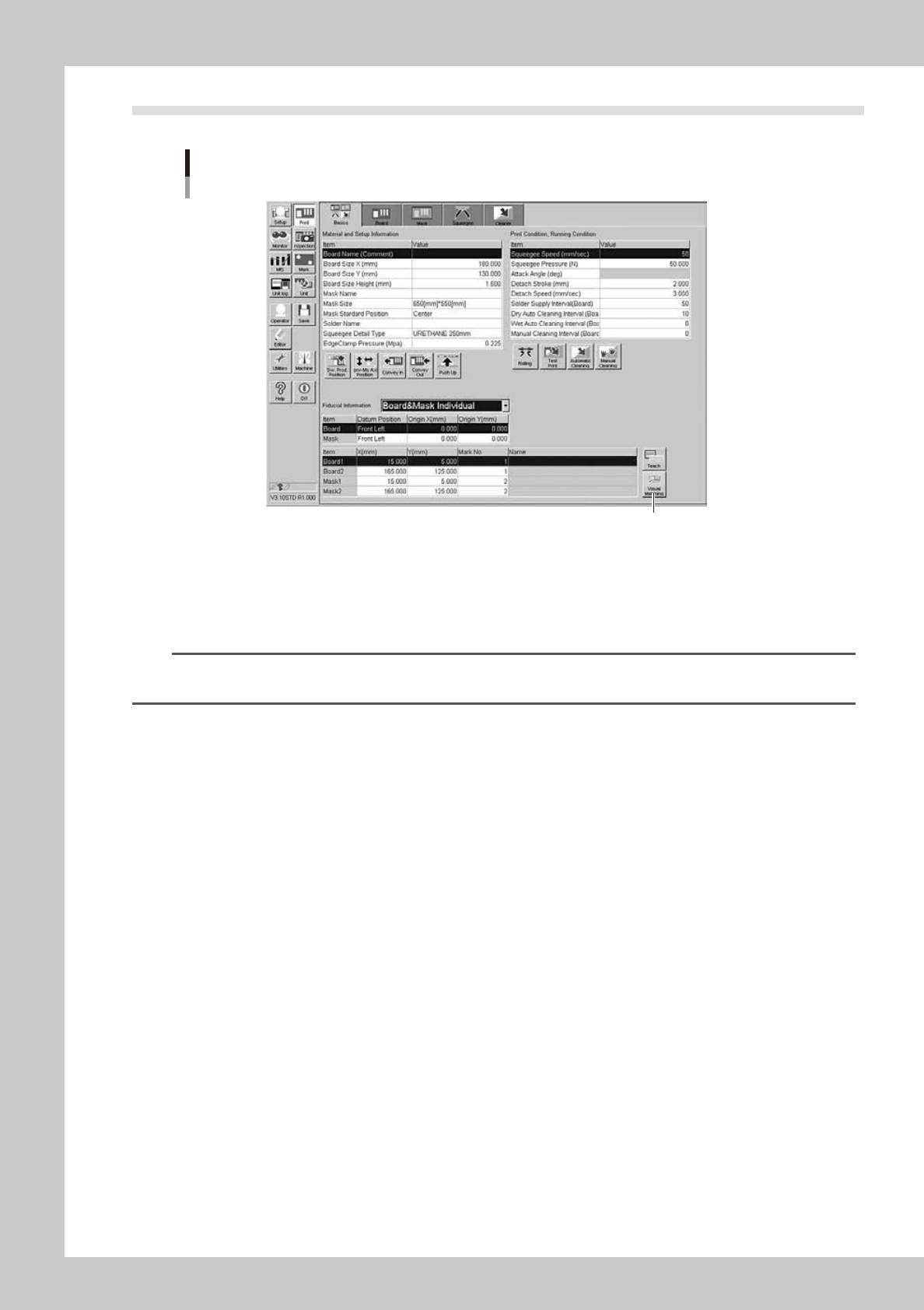
2.2 Alignment offset setting
Alignment offsets
[Visual Matching] button
64E04-L3-10
Press the [Visual Matching] button to open the Alignment Offset screen. Determine each offset value
while carefully checking the screen.
Since the graphic alignment is used for this alignment offset setting, set values in the [Mask Offset
X(mm)], [Mask Offset Y(mm)], and [Mask Offset R(DEG)] fields you can check on the screen.
n
NOTE
For more details about how to correctly use the graphic alignment, see Chapter 4, “Graphic alignment”, in this
manual.