YSP_Users_E.pdf - 第57页
1-15 1 Part names and functions 4.3 Board carr y-in and carr y-out conveyors T he carry-in conveyor recei ves a board from the upstream machine (loader , etc.) and brings the board onto the board clamp table. T he carry-…
1-14
1
Part names and functions
l
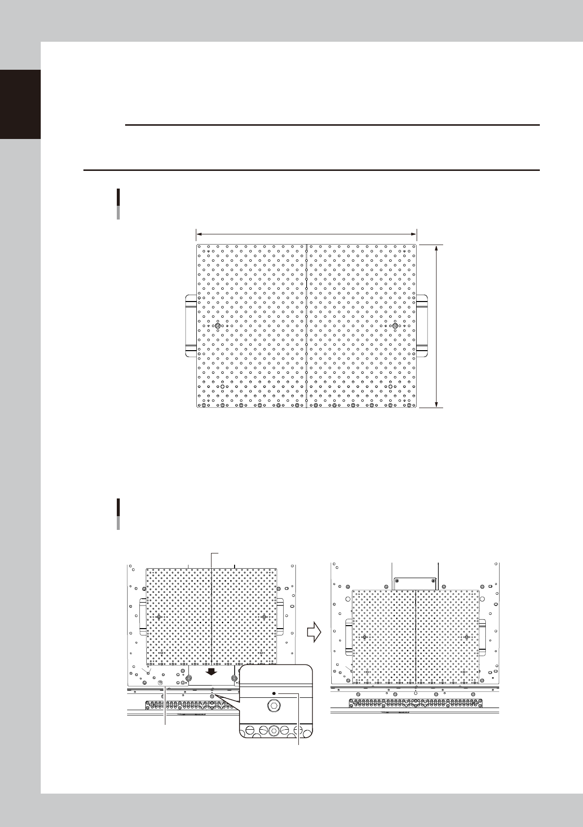
Medium-sized matrix plate (option)
When medium-sized (L 330 × W 250 mm) boards are manufactured, the machine can be prepared for the manufacture
with one medium-sized matrix plate. The conveyor unit can be easily changed in setup for manufacture of medium-sized
boards.
c
CAUT ION
If the machine has an old type of push-up plate, the medium-sized matrix plate cannot be installed. Check the center
line of the push-up plate shown in the following figure (installation of matrix plate) to see whether the plate of your
machine is of the new type.
Medium-sized matrix plate
L : 330mm
Applicable board size: 330 × 250 mm (medium size)
W : 245mm
63125-L3-00
n
How to install
Align the center line of the Medium-sized matrix plate on the center hole of the conveyor plate. Then, set the Medium-
sized matrix plate along the front surface of the push-up plate.
Installation of matrix plate
Push-up plate side face
Conveyor plate center hole
Matrix plate center line
■ Before installation ■ After installation
63126-L3-00
1-15
1
Part names and functions
4.3 Board carry-in and carry-out conveyors
The carry-in conveyor receives a board from the upstream machine (loader, etc.) and brings the board onto the
board clamp table. The carry-out conveyor receives the board from the board clamp table and transfers the
board to the downstream machine. The conveyor width is automatically adjusted according to the board width
(Board Size Y). The carry-in and carry-out conveyor positions change depending on the board transport
direction. (Right-to-left flow on standard machines)
Board carry-in and carry-out conveyors
Example of right → left flow
Carry-out side (example using extended exit conveyor) Carry-in side
63116-L3-00
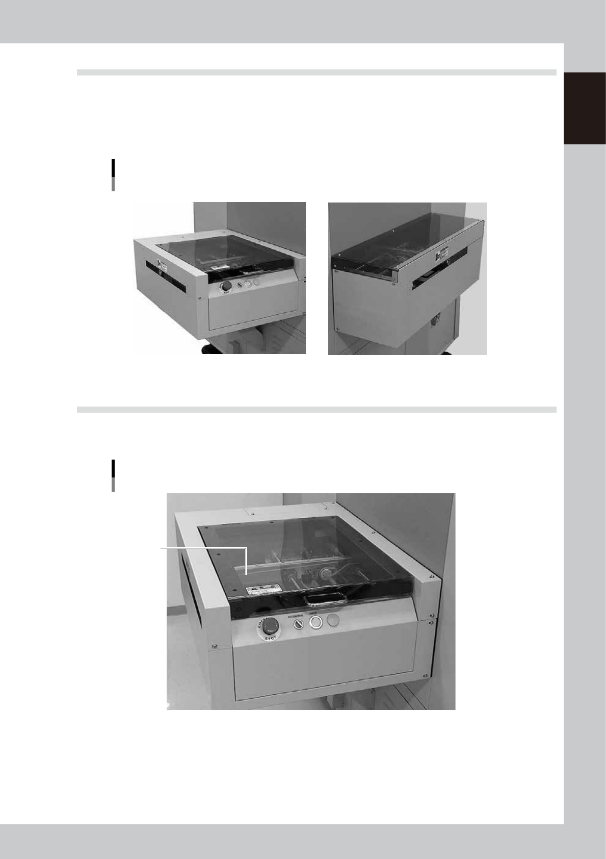
4.4 Extended exit conveyor (option)
YSP machines equipped with an optional extended exit conveyor allow making a visual check of printed solder
paste at the conveyor exit.
Extended exit conveyor (option)
Safety cover
63117-L3-00
1-16
1
Part names and functions
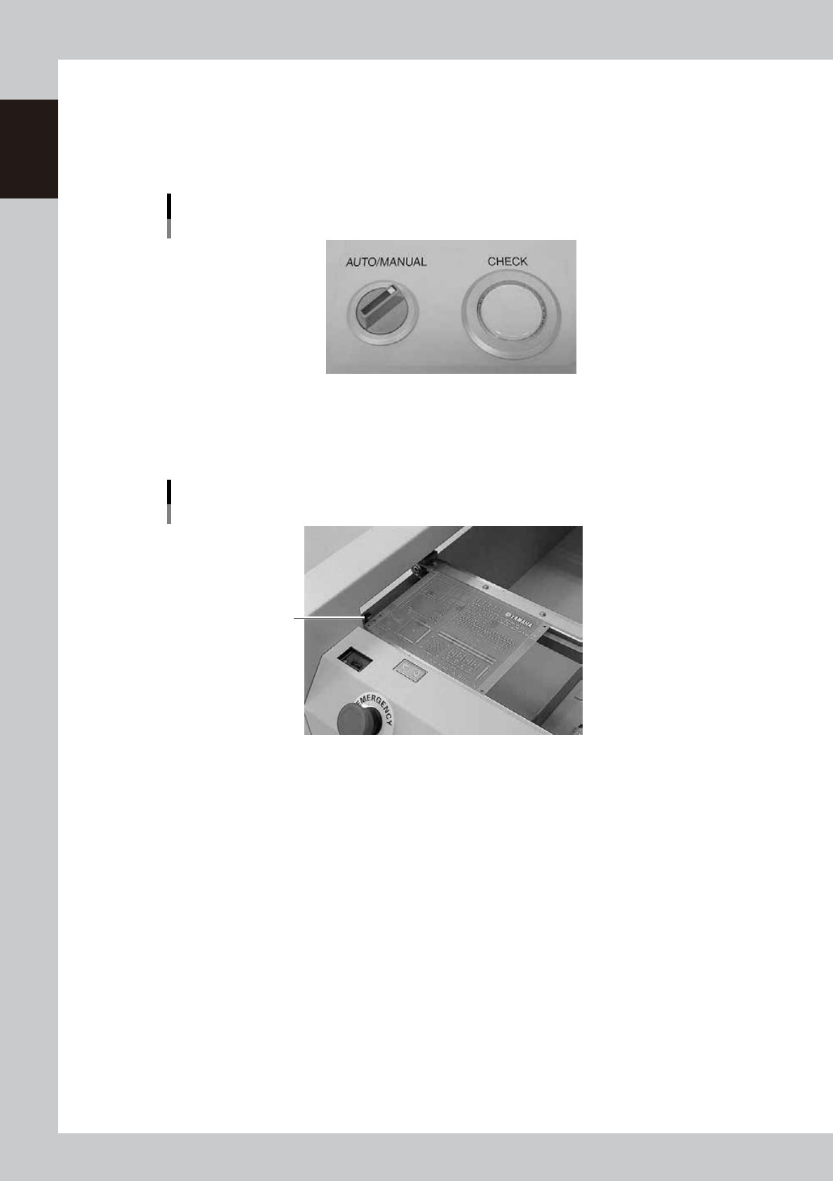
4.4.1 MANUAL mode
When you want to visually inspect solder paste printed on a board, set the AUTO/MANUAL switch to
"MANUAL". When MANUAL mode is selected, the board transferred from the board clamp table temporarily
stops at the exit on the extended conveyor. You can inspect the printed solder paste visually with the procedure
described below.
AUTO/MANUAL switch
MANUAL mode
63118-L3-00
1
Make sure that a board has stopped on the extended exit conveyor.
The CHECK button lamp lights up when a board stops in the exit position (exit stopper position) on the
extended exit conveyor.
Temporary board stop position
Exit stopper
63119-L3-00
2
Inspect the board.
You can pick up a board from the extended exit conveyor and inspect how accurately the solder paste
is printed on the board.
3
Return the board to the extended exit conveyor after inspecting it.
4
Press the CHECK button.
The CHECK button lamp turns off and the board is then transferred to the downstream machine.