YSP_Users_E.pdf - 第139页
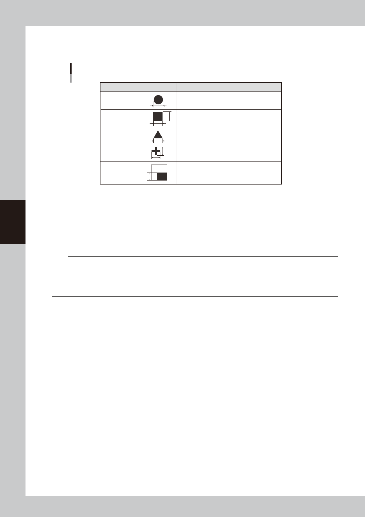
4-36 4 Creating and setting the data A, B: Mark Out Size Referring to the table below , enter the correct v alue in the mark size. T he "Mark Size X" is display ed when "Mark T ype" on the [Basic] tab…
4-35
4
Creating and setting the data
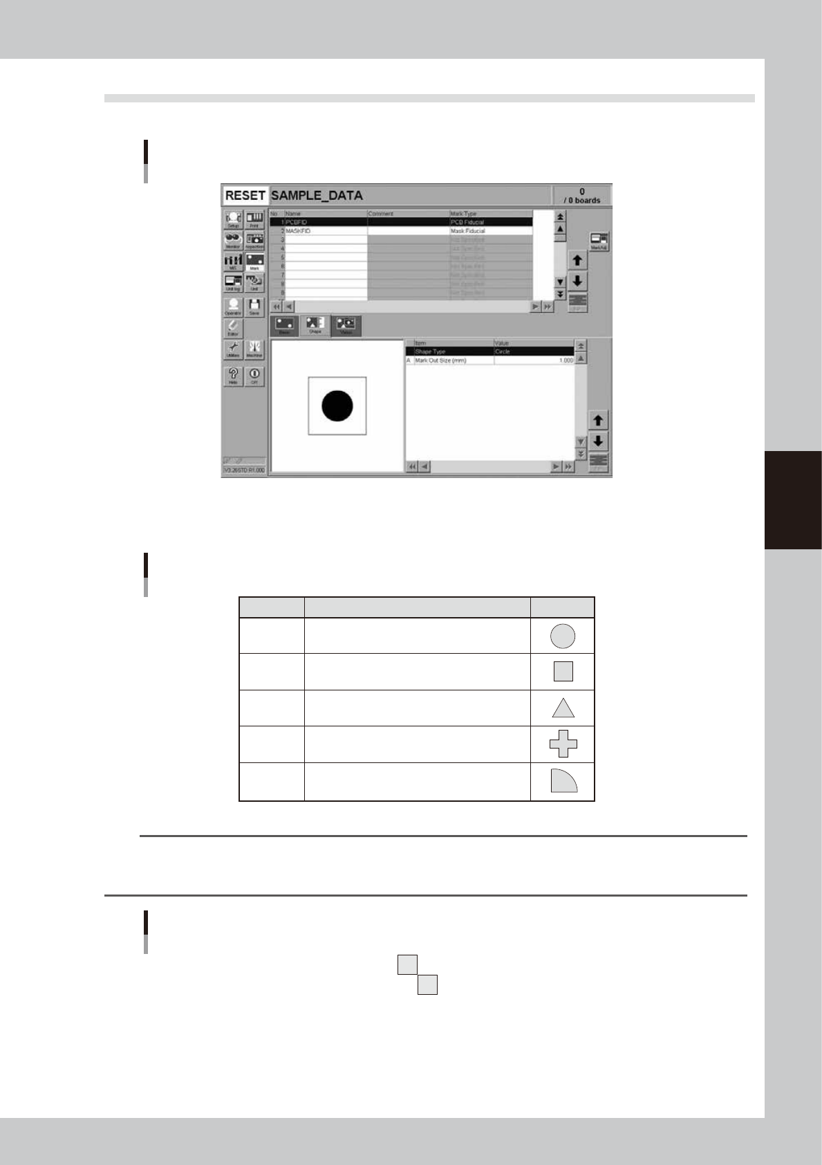
7.3 Shape parameters
In the list on the [Mark]-[Shape] tab, set the following parameters relating to mark shape.
Shape parameters
64431-L3-20
Shape Type
The "Shape Type" can be selected from the following 5 types.
Shape Type settings
Setting Description
Example
Circle
Square
Triangle
Sp. Shape
Corner
Select to detect a circular mark.
Select to detect a square mark.
Select to detect an equilateral triangular mark.
Select to detect a special mark other than above.
Select to detect a corner of a pattern as a mark.
63419-L3-00
TIP
If using a special mark composed of two or more objects, set the Algorithm parameter (described later) to "Pattern".
In this case, the "Shape" parameter is ignored during mark recognition so you can set this parameter to any type. (For
more details, see "7.5 Pattern matching"
Example of special mark
63420-L3-00
4-36
4
Creating and setting the data
A, B: Mark Out Size
Referring to the table below, enter the correct value in the mark size. The "Mark Size X" is displayed when "Mark Type"
on the [Basic] tab is set to "Sp. Shape".
X
X
Y
Y
Mark Out Size settings
Example
Mark Out Size setting Shape Type
Circle
Square
Triangle
Sp. Shape
Corner
Enter the diameter.
Enter the length of each side.
Enter the length of one side.
Enter the X length for the MarkOutSize X, and the Y
length for the MarkOutSize Y.
Enter the length of the shorter side displayed within the
search area.
63421-L3-00
C: Mark Area
Enter the area of the mark in units of square millimeters. This parameter is displayed only when "Shape Type" on the
[Shape] tab is set to "Sp. Shape".
D: Outline
Enter the perimeter length of the mark in units of millimeters.
This parameter is displayed only when "Shape Type" on the [Shape] tab is set to "Sp. Shape".
n
NOTE
A recognition error may occur due to environmental conditions such as illumination. In such cases, enter a larger
value than previously used for
"Tolerance" of the Vision parameters, or set the tolerance to 100%, then perform the
vision test in the Mark Adjust mode and enter the obtained data on the area and perimeter. (The mark area and
perimeter values are displayed after the vision test is complete.) Return the tolerance to the original value after the
data is obtained.
4-37
4
Creating and setting the data
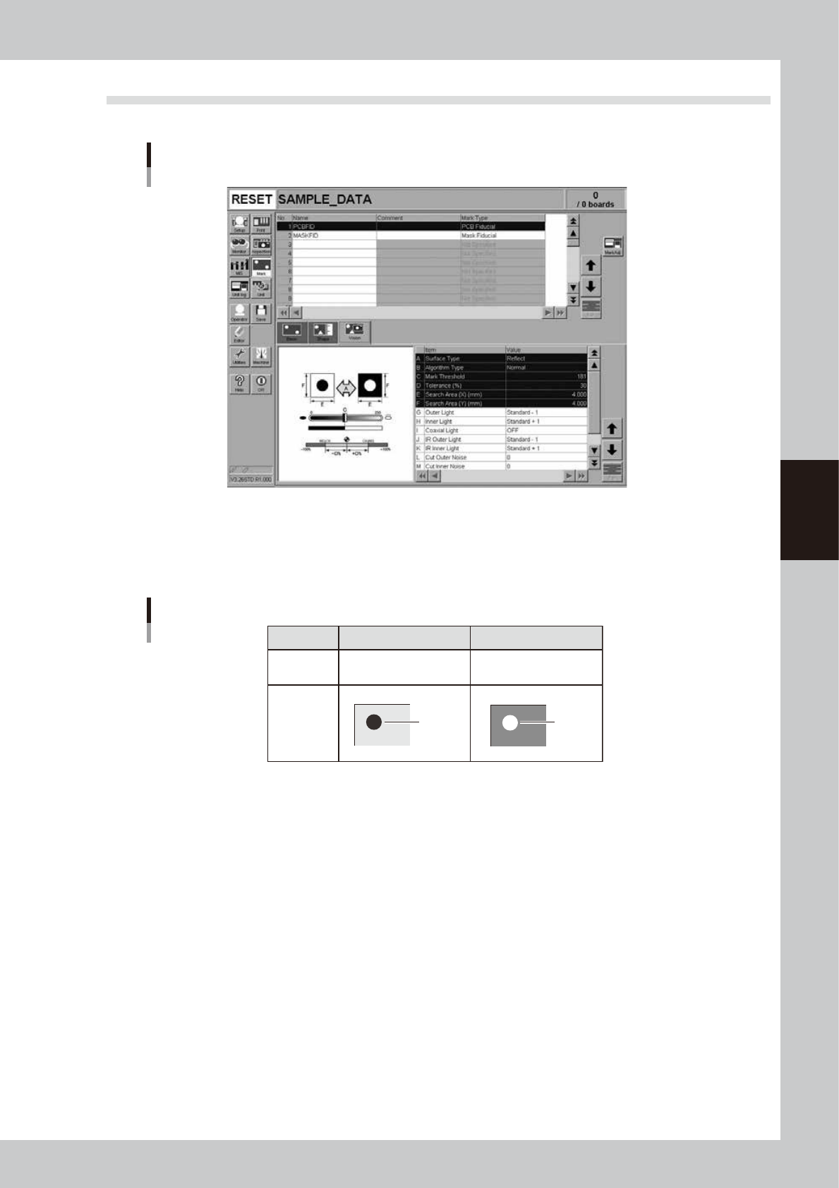
7.4 Vision parameters
In the list on the [Mark]-[Vision] tab, set the following parameters used for mark recognition.
Vision parameters
64432-L3-20
A: Surface Type
This specifies the bright and dark relation between the mark surface and the surrounding area. Select "NonReflect" when
the mark is darker than the surrounding area. Select "Reflect" when the mark is brighter than the surrounding area as
shown below.
NonReflect
Board is brighter than mark.
Reflect
Mark is brighter than Board.
Setting
Brightness
comparison
Image
Mark
Mark
Surface Type setting
63423-L3-00
B: Algorithm Type
There are 5 algorithm types selectable for mark recognition.
Normal
In typical recognition, all types of marks should be set to "Normal". Try setting to other parameters if the mark cannot
be recognized with the "Normal" setting.
Special 1
Select this if the mark cannot be recognized with the "Normal" setting.
Special 2
Select this if the mark which cannot be recognized with the "Normal" setting has a cutout area.
PTRN Outline, PTRN GrayLev, PTRN Whole
Select these parameters when the "Shape Type" parameter is set to "Pattern". For more details, refer to "2. Pattern
matching" in Chapter 6.
C: Mark Threshold
This is the threshold level for the binary image used to recognize the mark. An optimum threshold level can be found in
the Mark Adjust mode explained later in this section.
D: Tolerance
This specifies a tolerance percentage for the mark size when the mark is recognized with the vision camera. (Typically
this should be set to "30".)