YSP_Users_E.pdf - 第41页
iii About this manual 1.3 Page layout T he description below shows a typical page la yout used in this manual. 3-5 3 Daily operation 4. Changing the conveyor unit setup When producing boards that are different from the p…

ii
About this manual
1.2 Contents of each chapter
This manual is comprised of the following chapters. The appendix at the end of this manual gives quick
reference tables for the board support jig combination and applicable masks (stencils). An index is also
provided at the end of this manual to provide easy access to information located throughout the manual.
Chapter 1 Part names and functions
This chapter explains major part names and functions of the machine which you should know before attempting
operation.
Chapter 2 Basic operations
This chapter explains how to start up the machine and turn it off, as well as the basic menus and buttons displayed on
the screen for machine operation and data input.
Chapter 3 Daily operation
Chapter 3 describes the routine operation for board production including the conveyor unit setups, and also explains
how to read the production history data.
Chapter 4 Creating and setting the data
Chapter 4 explains the basic procedures for creating board data and also making basic settings for various parameters.
Chapter 5 Managing the data
This chapter explains how to back up data and make a user database, as well as how to view and save the production
and machine operation logs.
Chapter 6 Other functions
This chapter explains efficient data creation tools, such as coordinate data teaching and trace functions, and manual
operation.
Chapter 7 Replacing the consumable parts
This chapter explains how to replace the cleaning gauze roll and cleaning alcohol, etc.
Chapter 8 Inspection and maintenance
Chapter 8 describes checkpoints and procedures for daily and periodic inspections that you should perform. Additionally,
the grease-up work is explained using the list of lubrication locations.
Appendix
In the appendix, you will find necessary machine specifications, such as air pressure settings, power supply voltage, and
input and output signals for connections between machines, and the board support jig combination table and applicable
masks (stencils) used as reference data for the setup work.
Printing guide
This guide explains the flow of the condition setting (data setting) and the setup work necessary to perform the printing
with excellent quality.
Additionally, describes the relationship between the print trouble symptom and the conditions that may be the cause of
the trouble.
iii
About this manual
1.3 Page layout
The description below shows a typical page layout used in this manual.
3-5
3
Daily operation
4. Changing the conveyor unit setup
When producing boards that are different from the previous production board, you need to change the
conveyor unit setup to match the selected board. (This procedure is not necessary when you are producing
the same board as last time.)
c
CAUTION
When producing board whose width is narrower than the previous production board, remove in advance the push-up
jigs (or backup pins) from the push-up plate.
1
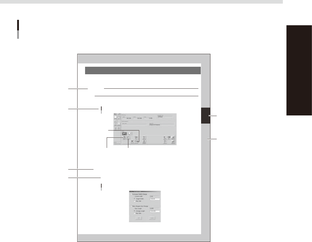
Open the [Unit]-[Conveyor] tab.
The buttons on this screen are used in the following steps to change the conveyor unit setup.
[Unit]-[Conveyor] tab
Step 3:
[Conv-MS Axis Position] button
Step 2:
[SW. Prod. Position] button
Step 6:
[Convey In]
button
64306-L3-00
2
Press the [SW. Prod. Position] button.
The conveyor table rises to the same height as the conveyor rails and the squeegee head moves to the
escape position (inner side).
3
Adjust the conveyor width and main stopper position.
1. Press the [Conv-MS Axis Position] button.
The dialog box appears for changing the conveyor width and main stopper position.
2. Check the board width and length shown in the dialog box and press the [OK] button.
The conveyor width and main stopper position are automatically changed to match the board size.
Dialog box for changing conveyor width and main stopper position
64307-L3-00
Typical page layout
Step
Chapter number
Chapter title
Sub step or
description of step
Figure, picture
or table caption
Note, Caution
or Warning
63003-L3-00
n
Step
This describes the procedure for each operation.
n
Substep or description of step
This provides detailed information on the steps in each procedure.
n
Illustration or table caption
This is the title of the illustration or table and appears at the upper left.
n
Note, Caution or Warning
These are explained in detail in "Safety instructions".

Chapter 1 Part names and functions
This chapter explains YSP major part names and functions. Make sure that you understand the location and function of each
part before attempting machine operation.
Contents
1. YSP main unit 1-1
2. Operation panels and data input units 1-4
2.1 Operation panel buttons 1-5
2.2 Keyboard and mouse 1-6
2.3 Liquid crystal touch screen (option) 1-6
3. Printing section 1-7
3.1 Squeegee head and printing table 1-7
3.2 3S squeegee 1-8
3.3 Double squeegee (option) 1-9
4. Conveyor unit 1-10
4.1 Board clamp unit (board clamp table) 1-10
4.2 Board support 1-11
4.3 Board carry-in and carry-out conveyors 1-15
4.4 Extended exit conveyor (option) 1-15
4.4.1 MANUAL mode 1-16
4.4.2 AUTO mode 1-17
5. Cleaning unit 1-18
5.1 Cleaning unit 1-18
5.2 Suction unit 1-19
6. Camera unit 1-20
7. Servo-controlled axes 1-21