YSP_Users_E.pdf - 第261页
A-10 A Appendix Number of rows Applicable board size (W) Board support jig type/Q'ty used Pins combined (rows) A B C 35 255 to 262 2 1 0 0 36 262 to 269 2 1 0 1 37 269 to 276 2 1 0 2 38 276 to 283 2 1 1 0 39 283 to …
A-9
A
Appendix
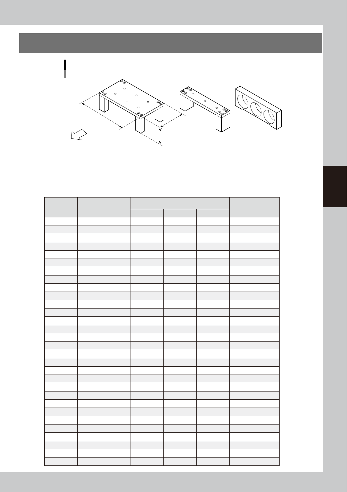
4. Board support jig combinations
Board support jig dimensions and combination table
Front of machine
(89mm, 15 rows of pin insertion holes) (33mm, 5 rows of pin insertion holes) (19mm, 3 rows of pin insertion holes)
A B C
W
L : 159mm
H : 55mm
63010-L3-00
The table below shows how many A to C blocks are arranged in the W direction and how many pin rows are
used for each board size.
Combine blocks and pins suitable for the board size while referring to the table below.
n
Board support jig combination table
Number of
rows
Applicable board size
(W)
Board support jig type/Q'ty used
Pins combined
(rows)
A B C
5 50 to 52 0 1 0 0
6 52 to 59 0 0 2 0
7 59 to 66 0 0 2 1
8 66 to 73 0 1 1 0
9 73 to 80 0 1 1 1
10 80 to 87 0 2 0 0
11 87 to 94 0 2 0 1
12 94 to 101 0 1 2 1
13 101 to 108 0 2 1 0
14 108 to 115 0 2 1 1
15 115 to 122 1 0 0 0
16 122 to 129 0 2 2 0
17 129 to 136 0 2 2 1
18 136 to 143 1 0 1 0
19 143 to 150 1 0 1 1
20 150 to 157 1 1 0 0
21 157 to 164 1 0 2 0
22 164 to 171 1 0 2 1
23 171 to 178 1 1 1 0
24 178 to 185 1 1 1 1
25 185 to 192 1 1 1 2
26 192 to 199 1 1 2 0
27 199 to 206 1 1 2 1
28 206 to 213 1 2 1 0
29 213 to 220 1 2 1 1
30 220 to 227 2 0 0 0
31 227 to 234 1 2 2 0
32 234 to 241 1 2 2 1
33 241 to 248 2 0 1 0
34 248 to 255 2 0 1 1
A-10
A
Appendix
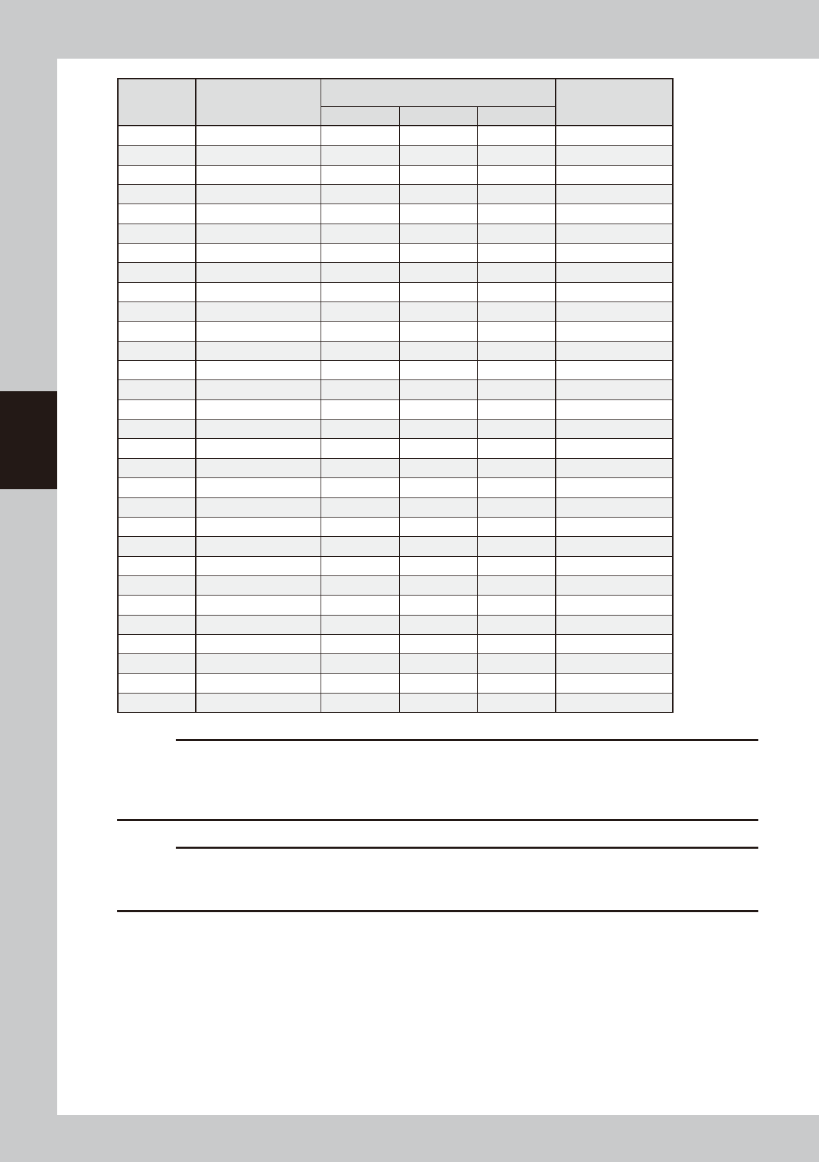
Number of
rows
Applicable board size
(W)
Board support jig type/Q'ty used
Pins combined
(rows)
A B C
35 255 to 262 2 1 0 0
36 262 to 269 2 1 0 1
37 269 to 276 2 1 0 2
38 276 to 283 2 1 1 0
39 283 to 290 2 1 1 1
40 290 to 297 2 2 0 0
41 297 to 304 2 2 0 1
42 304 to 311 2 2 0 2
43 311 to 318 2 2 1 0
44 318 to 325 2 2 1 1
45 325 to 332 3 0 0 0
46 332 to 339 3 0 0 1
47 339 to 346 3 0 0 2
48 346 to 353 3 0 1 0
49 353 to 360 3 0 1 1
50 360 to 367 3 1 0 0
51 367 to 374 3 1 0 1
52 374 to 381 3 1 0 2
53 381 to 388 3 1 1 0
54 388 to 395 3 1 1 1
55 395 to 402 3 2 0 0
56 402 to 409 3 2 0 1
57 409 to 416 3 2 0 2
58 416 to 423 3 2 1 0
59 423 to 430 3 2 1 1
60 430 to 437 3 2 1 2
61 437 to 444 3 2 2 0
62 444 to 451 3 2 2 1
63 451 to 458 3 2 2 2
64 458 to 460 3 2 2 3
c
CAUTION
The board support jig is secured by press-fitting it into the holes in the matrix plate. Mount the board support jig after
checking that no solder or foreign matter exists on the matrix plate.
Additionally, if the board support jig is placed so that it protrudes from the matrix plate, this may cause damage to the
machine.
c
CAUTION
The board support jigs explained in this section are specially designed for the YSP. If these board support jigs are used
for other machine, this may cause serious damage to the machine.
Therefore, never use these board jigs for a machine other than the YSP.

Printing guide
Contents
1. Flow of printing condition setting E-1
2. Data and condition setting E-2
2.1 Material and setup information E-2
2.2 Alignment offset setting E-4
2.3 Rolling E-5
2.4 Printing and production conditions E-6
3. Details of each parameter item E-7
3.1 Board clamp E-7
3.1.1 Edge clamp pressure E-7
3.1.2 Backup jig E-8
3.2 Board and mask mark recognition (Mark position) E-8
3.3 Alignment offset E-8
3.4 Squeegee (Rolling) E-9
3.4.1 Squeegee speed E-9
3.4.2 Squeegee pressure E-9
3.4.3 Attack angle (degree (°)) E-9
3.5 Solder supply interval E-10
3.6 Detach pattern E-10
3.6.1 Board separation speed E-10
3.6.2 Board separation distance E-11
3.7 Cleaning E-11
3.7.1 Cleaning interval E-11
3.7.2 Cleaning repeat E-11
3.7.3 Cleaning speed E-11
4.
Causes of troubles predicted from symptoms (Appendix)
E-12
4.1 Positional deviation E-12
4.2 Blur E-12
4.3 Insufficient filling E-12
4.4 Solder spread, solder bridge E-13
4.5 Scraping trouble E-13
4.6 Solder enlargement E-13
4.7 Solder chipping, mask remaining E-13
EUL3200_AP