YSP_Users_E.pdf - 第143页
4-40 4 Creating and setting the data 5 Check the tr ace position. Check that the mark is aligned with the center of the vision monitor , at the point shown below. If the position has shifted, open the [Print]-[Board] tab…
4-39
4
Creating and setting the data
7.5 Mark Adjust mode
This operation checks whether the parameter settings are correct. For parameters which are unspecified, the
optimal values can be obtained by performing "VISION TEST" here.
1
Select the mark data.
In the data list on the Mark screen, line up the cursor with the mark data you want to check.
2
Press the [Mark Adjust] button to enter the Mark Adjust mode.
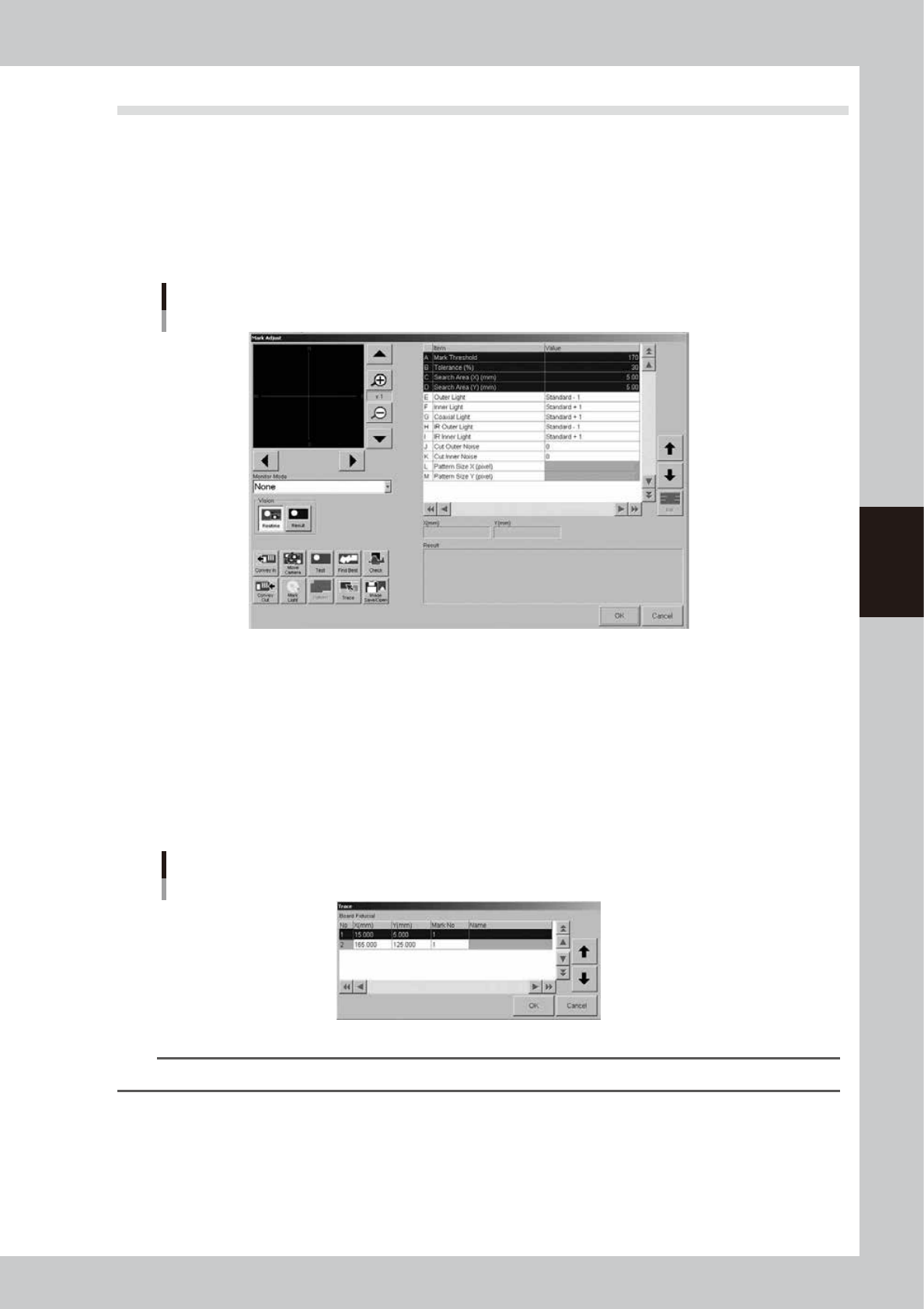
The Mark Adjust screen appears as shown below.
Mark Adjust screen
64433-E3-00
3
Set the board on the conveyor and clamp it.
To clamp the board, press the [Convey In] button and follow the message that appears.
When adjusting fiducial marks on a mask, clamp the mask on the printing table.
4
Perform a trace to the mark.
1. Press the [Trace] button to open the "Trace" dialog box.
2. Press the [OK] button to perform a trace to the selected mark position.
For board fiducial marks, the board moves to a point just under the board vision camera. For mask
fiducial marks, the mask vision camera moves to a point directly under the mark on the mask frame.
Trace dialog box
64434-L3-00
TIP
For details on the trace and teaching functions, see "1. Teach and trace" in Chapter 6.
4-40
4
Creating and setting the data
5
Check the trace position.
Check that the mark is aligned with the center of the vision monitor, at the point shown below. If the
position has shifted, open the [Print]-[Board] tab (or [Print]-[Mask] tab) and reteach the mark
coordinate.
Mark trace position
Shape Type Teaching point Example
Circle, Square
Triangle, Sp. Shape
Center of mark
Corner of mark
Center of a square
edge line
Center of a round edge
Corner
TopEdge
CirEdge
: Center of crosshairs
63425-L3-00
6
Adjust the light levels.
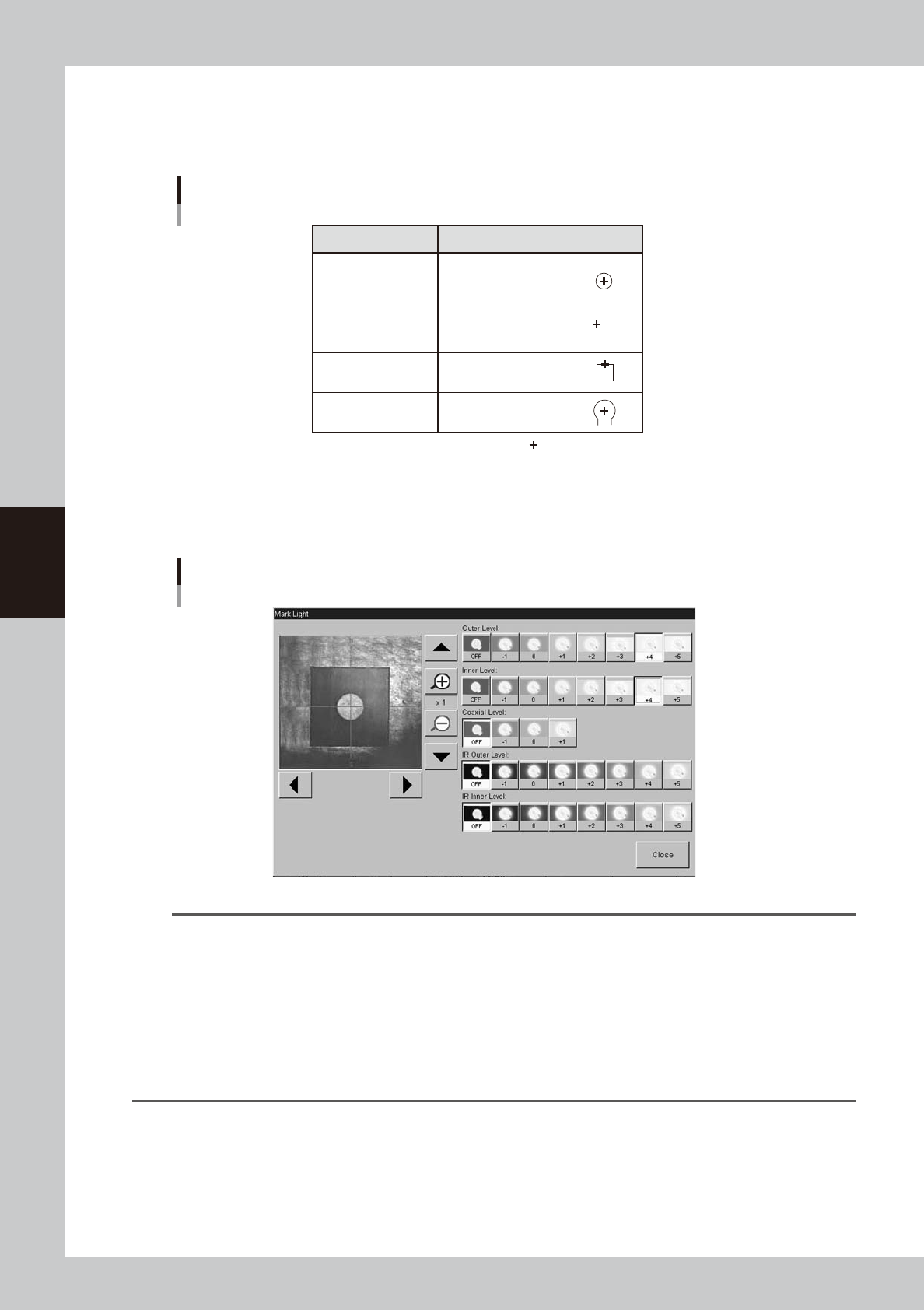
Press the [Light] button to open the light level adjustment screen, and adjust the light level in each
lighting zone so that the mark can be most clearly viewed on the vision monitor.
Light level adjustment
64435-L3-00
TIP
Optimum light levels depend on the materials of the board, mask frame and mark. Use the following method to find
optimum light levels.
1. Turn off all light units.
2. Turn on, one at a time, "Outer Light", "Inner Light", "Coaxial Light, "IR Outer Light" and "IR Inner Light" at the
maximum level, to see how clearly the mark can be seen.
3. Combine the light units that were effective, and adjust their light levels.
As a general guide for adjusting board mark lighting, try these suggestions.
• Flat surface marks reflecting light : "Coaxial Light" is effective.
• Flat surface marks made of copper oxide : "IR Inner Light" is effective.
• Marks with uneven surface diffusing light : "IR Outer Light" is effective.
4-41
4
Creating and setting the data
7
Press the [Find Best] button to find an optimum threshold level.
Pressing this button automatically finds an optimum threshold level for the mark, and the result is
displayed. If an error occurs, check the following points.
1. Press the [Cancel] button to return to the Mark screen, and then check whether parameters such as
"Mark Type", "Shape Type" and "Algorithm Type" are correct.
2. Recheck the light levels and make adjustments as needed.
3. Press the [Find Best] button again to find an optimum threshold level.
8
Press the [Test] button to perform the vision test.
When the result is successful, the adjustment is now complete.
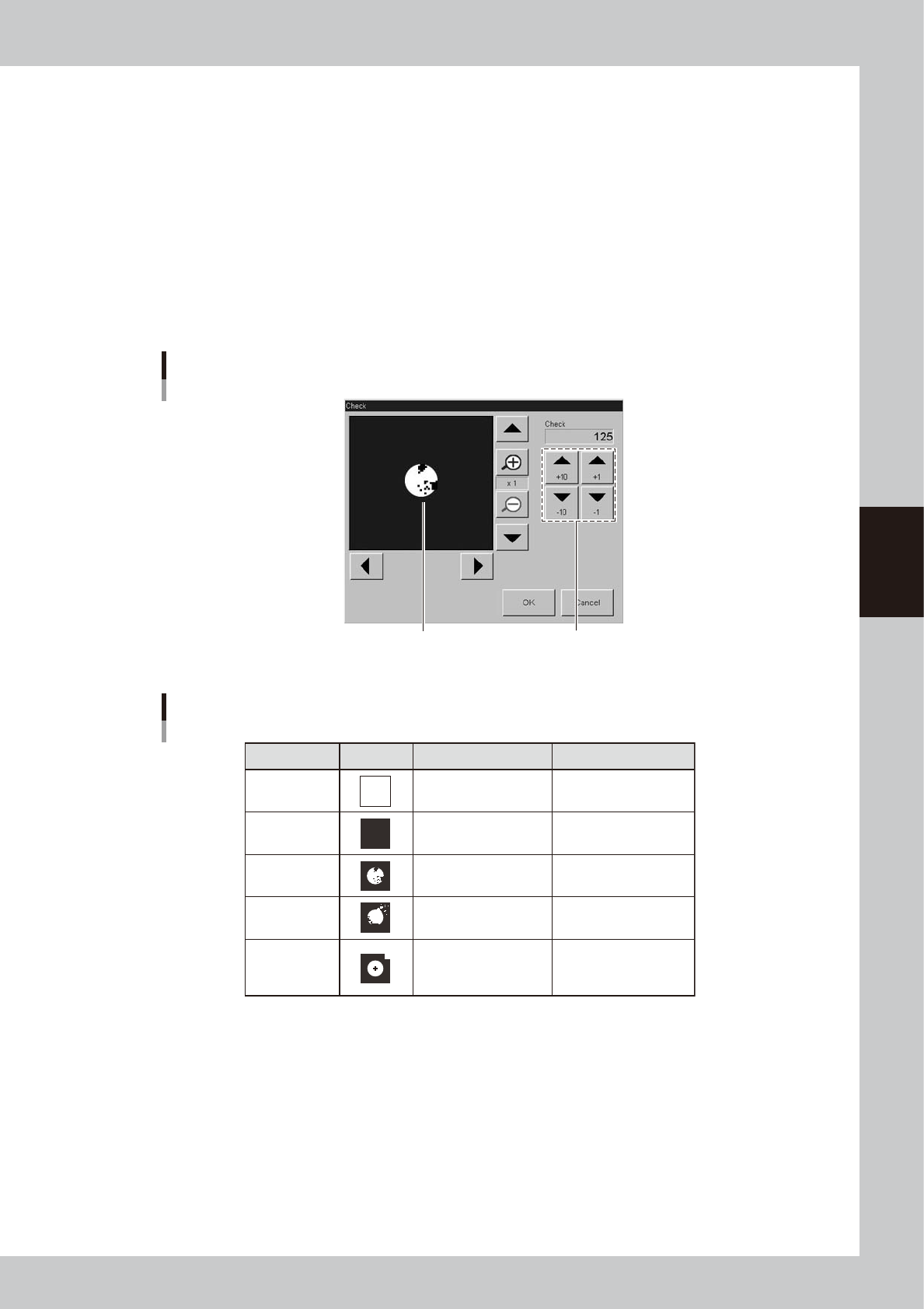
If the vision test result is a fail, press the [Result] button to display the binary image of the mark and
adjust the threshold level manually by referring the table below, so that the binary image is most clearly
displayed.
Binary mark image
Binary mark image and threshold level adjustment
Use these arrow buttons to adjust
the threshold level.
64436-L3-00
Binary image check and adjustment
State
All white
All black
Noise within
mark
Noise outside
of mark
Other than
mark in
search area
Image Countermeasure
Increase the threshold
level with the arrow
buttons.
Decrease the threshold
with the arrow buttons.
Increase the Cut Inner
Noise level.
Increase the Cut Outer
Noise level.
Reduce the Search
Area size.
Remarks
Adjust it till the mark is
displayed.
Adjust it till the mark is
displayed.
Refer to "Search Area"
explained previously.
Recognition time becomes
longer as the Cut Inner
Noise level is increased.
Recognition time becomes
longer as the Cut Outer
Noise level is increased.
63426-L3-00
9
Press the [Test] button to perform the vision test again.
Repeat this test several times. If no error is detected, each parameter is appropriate so the adjustment
is now complete.
0
Press the [OK] button to save the adjusted data.
The Mark Adjust screen closes and returns to the Mark screen.
q
Use the same procedure when adjusting other marks.