YSP_Users_E.pdf - 第121页
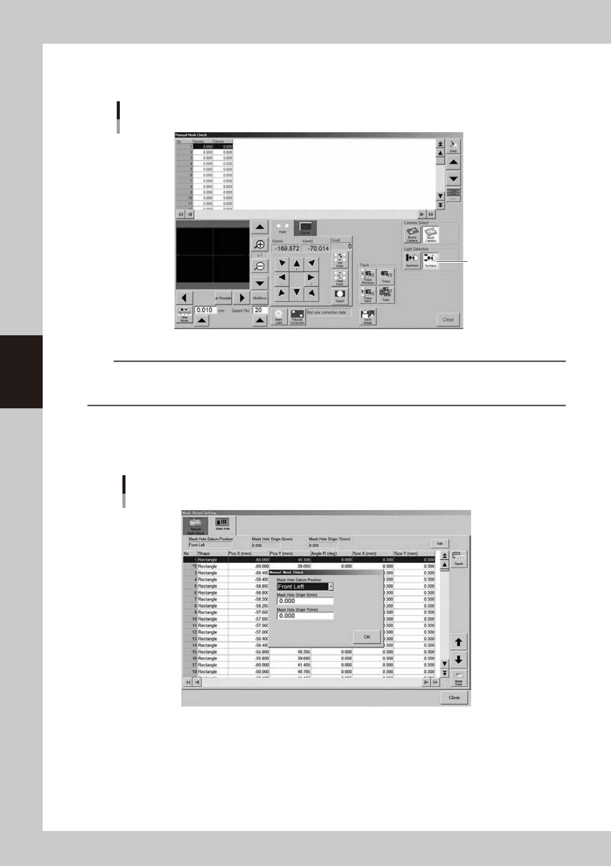
4-18 4 Creating and setting the data T o set the lighting for inspecting excess solder and flux spreading to the backside of the mask, press the [Light] button while the [Surface] button is depressed. Y ou can then chang…
4-17
4
Creating and setting the data
4.2 Mask data detail setting
l
Mask check positions
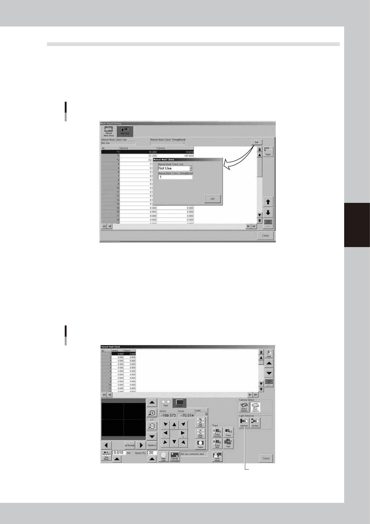
When you press the [Detail] button on the [Print]-[Mask] tab, the following dialog box appears for setting the mask check
positions. You can specify positions on the mask where you want make a visual check after solder printing. Pressing the
[Edit] button at the upper right opens the "Manual Mask Check" dialog box. Set whether to use this function or not. Also
set the board interval (number of boards) at which to make the visual check.
[Manual Mask Check] tab
64419-L3-20
l
Lighting setup for visual mask check
The lighting settings needed when making the mask aperture inspection (clogging inspection) and mask backside
inspection (inspection of excess solder spreading to backside) can be now separately set for each inspection and stored
as board data.
Pressing the [Teach] button after entering the mask inspection coordinates makes the following "Teach/Trace" window
appear. To set the lighting for the mask aperture clogging inspection, press the [Light] button while the [Aperture] button
is depressed. The lighting setup window then opens so you can change to a lighting level where you can easily check for
mask aperture clogging.
"Teach/Trace" window for visual mask check
[Aperture] button
[Aperture] button
64420-L3-00
4-18
4
Creating and setting the data
To set the lighting for inspecting excess solder and flux spreading to the backside of the mask, press the [Light] button
while the [Surface] button is depressed. You can then change to an optimum lighting level on the lighting setup window.
In either case, closing the window automatically stores the changes you made into the board data.
"Teach/Trace" window for visual mask check
[Surface] button
[Surface] button
64421-L3-00
n
NOTE
By storing the visual check lighting levels for the mask aperture and backside, you can switch to each lighting level by
just pressing the [Aperture] button for the mask aperture visual check or the [Surface] button for the mask backside
visual check.
l
Mask aperture (hole) coordinates setting
When you press the [Detail] button on the [Print]-[Mask] tab, the following dialog box appears for setting the mask
aperture coordinates.
[Mask hole] tab
64452-L3-00
This function is available only for machines equipped with an optional print inspection camera.
For details, see "2.3 Using the mask scan function" in the separate Option Manual.
4-19
4
Creating and setting the data
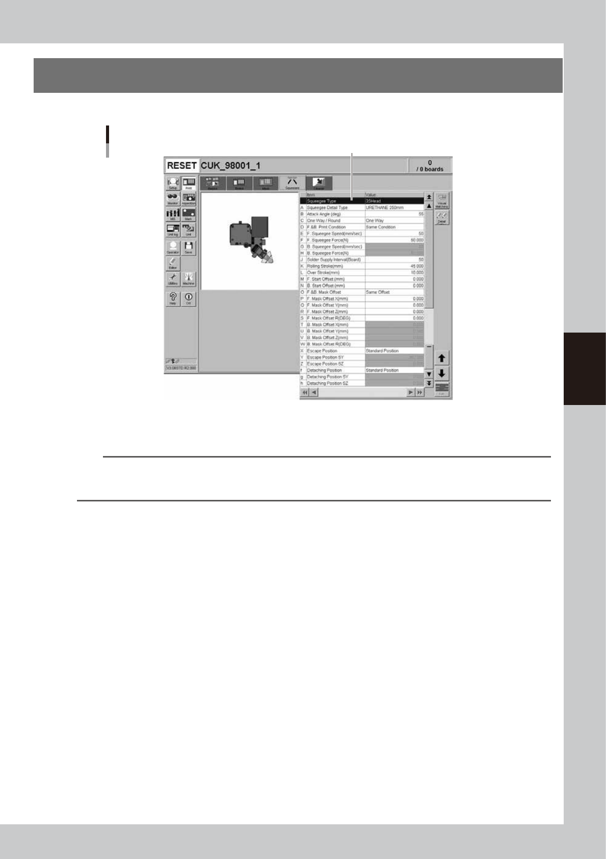
5. Squeegee data setting
The following parameter items can be checked and edited on the [Print]-[Squeegee] tab.
[Print]-[Squeegee] tab
1
64422-L3-00
1: Squeegee Type
Select "3S Head” when using the 3S squeegee head. When using an optional double squeegee, select "Double Squeegee".
TIP
The squeegee type has been set in the machine data prior to shipment according to the machine specifications. So
the same squeegee type as set in the machine data must be selected here. If not the same squeegee type, an error
is issued.
E: Solder Name
Enter the name or comment on the solder to be used. You can leave this field blank.
i: Squeeges Name
Enter the name or comment on the squeeges to be used. You can leave this field blank.
A: Squeegee Detail Type
Specify the squeegee type and size when the squeegee type is set to "3S Head” or “Double Squeegee".