JANETS_INM.pdf - 第201页
JaNets In structio n Manual 5. Shopflo or Setu p 5- 81 Operations Selectin g a machin e to be displ ayed When you se lect a Machi ne selecti on button, the fe eder layout scr een of t he corres pond ing machine c an be d…
JaNets Instruction Manual 5. Shopfloor Setup
5-80
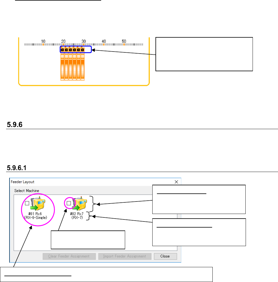
Head images display example
When you move the head images over a feeder assignment, feeders whose positions are
corresponding to the displayed heads are selected, and you can check the feeder attachment
position and the gap between heads.
Figure 5.9-49 Example of the displayed head images in Head Image Display mode
(when an RX-6 machine is used)
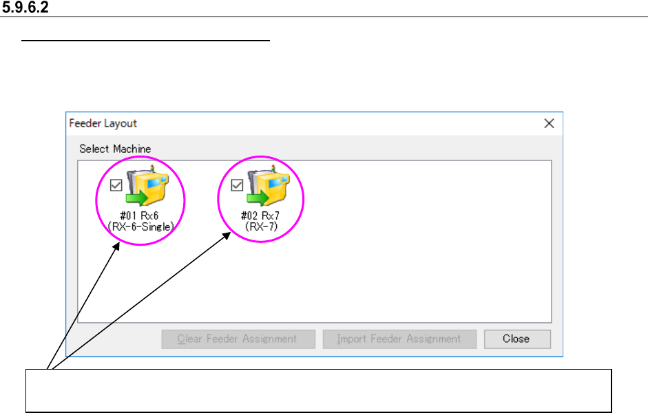
“Select Machine” Dialog Box
On this dialog box, you can check/edit the feeder assignment of a machine. Only if this “Select
Machine” dialog box is started up from the Program Editor, you can edit the assignment displayed
on the feeder layout screen.
Configuration of the “Select Machine” dialog box screen
Figure 5.9-50 “Select Machine” dialog box
* See Section 5.9.9 “Machine Icon Types” for machine type icons.
Since an RX-6 machine is equipped
with 6-axis heads, six head images
are displayed on the screen. You
can move the images as desired.
Machine selection button: Displays the machine configuration of the specified line.
Feeder layout display check
box
Machine type icon: Displays the
machine type, board transport
direction and reference side.
Machine information: Displays
the assignment number, machine
name and model name.
JaNets Instruction Manual 5. Shopfloor Setup
5-81
Operations
Selecting a machine to be displayed
When you select a Machine selection button, the feeder layout screen of the corresponding
machine can be displayed.
Figure 5.9-51 When two or more machines are selected on the “Select Machine” dialog box
Two or more feeder layout screens can be displayed at the same time. The check box of the Machine
selection button whose corresponding feeder layout screen is displayed is checked on the screen.
JaNets Instruction Manual 5. Shopfloor Setup
5-82
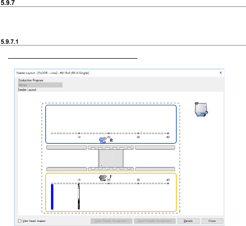
Feeder Layout Screen
Various types of feeders and/or trays whose component supply position is specified are displayed
here. When “Auto” is selected in the “Machine” or “Bank” field, the corresponding data is not
displayed on the screen.
Configuration of the “Feeder Layout” screen
When only a production program is to be referred
Figure 5.9-52 “Feeder Layout” screen