JANETS_INM.pdf - 第204页
JaNets In structio n Manual 5. Shopflo or Setu p 5- 84 Machine Icon Ty pes T able 5. 8.9-1 Machine ico ns and th eir specif ications Icon Setting Applicabl e machin e models Board transport directio n: Left to right Refe…
JaNets Instruction Manual 5. Shopfloor Setup
5-83
Color of an assigned feeder
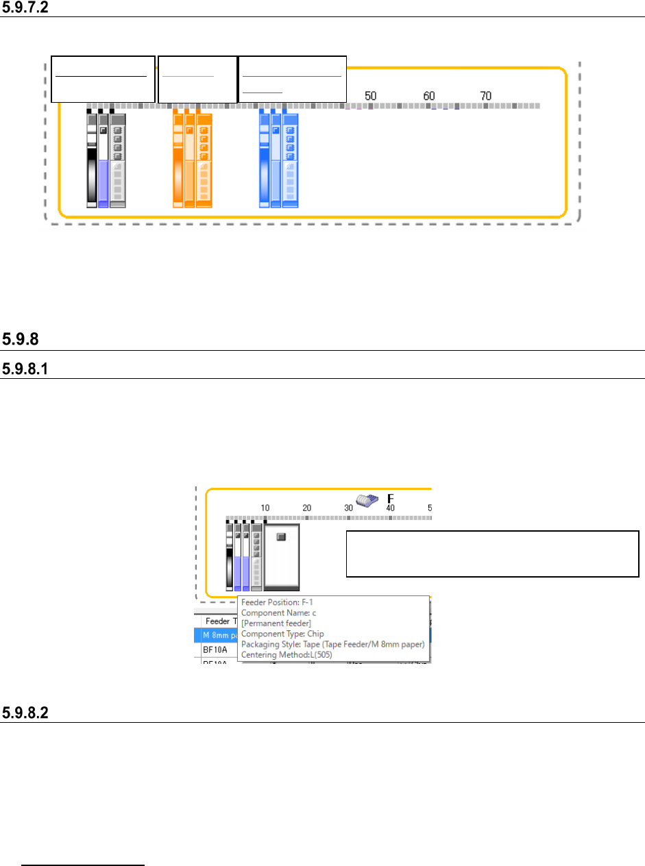
A feeder assigned on the layout screen is colored depending on its condition as shown below.
Figure 5.9-53 Colors of a feeder icon (normal condition, selected, set as a permanent feeder.)
* When the condition of each lane is different from that of a feeder itself if it has two or more
lanes, each lane and the feeder are colored depending on its condition respectively.
Operations(Feeder layout screen)
Displaying the details of a feeder
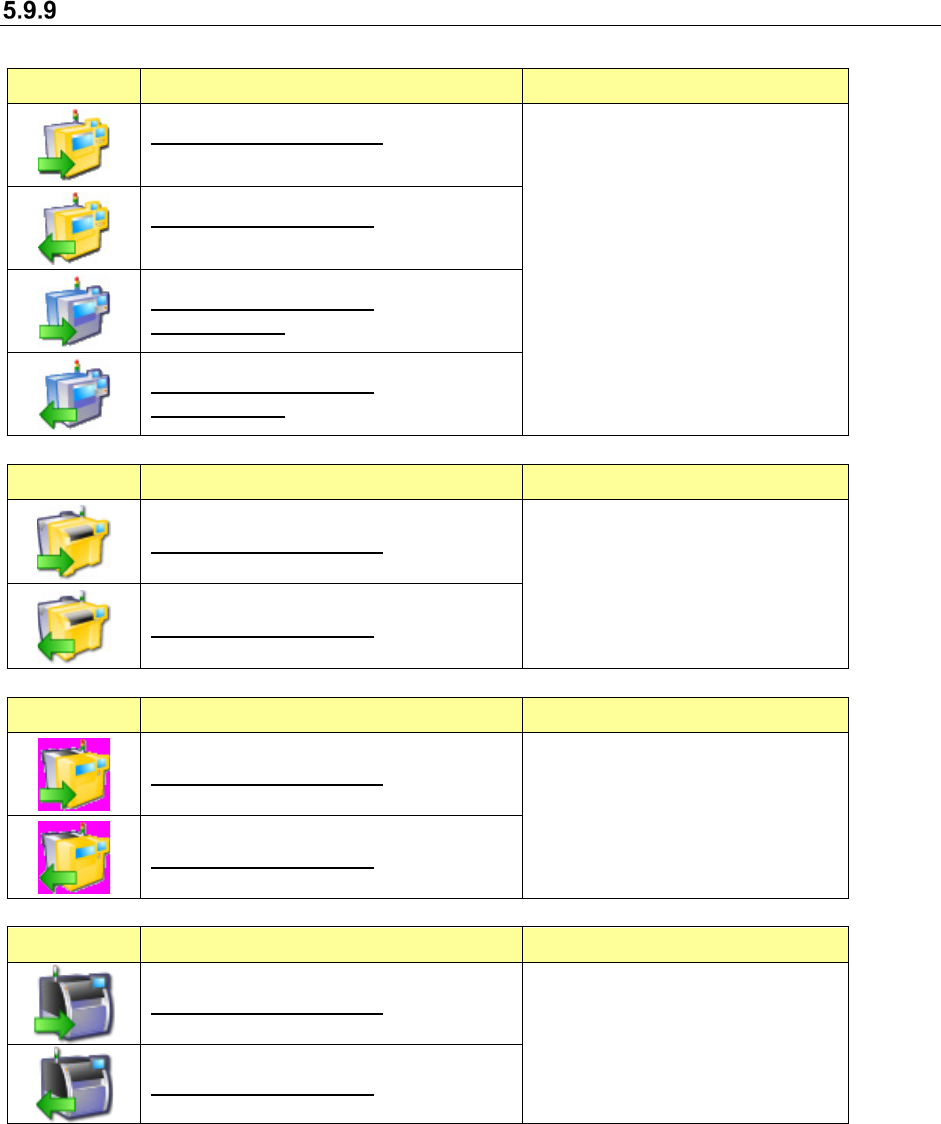
When you move the cursor over a feeder, the following items are displayed. When you move the
cursor over a permanent feeder, “[Permanent]” is additionally displayed at the component supply
position. When a feeder has two or more lanes, the lane number is displayed also. When you
move the cursor over a DTS, the tray level number from which components are supplied is
displayed.
Figure 5.9-54 Example of the “Feeder Layout” window (as a pop-up window)
Editing on the “Feeder Layout” screen
When you select the <Close> button on the “Select Machine” dialog box after editing data, the
message asking you whether to reflect your editing in the program data appears on the screen.
When you select the <Yes> button, your editing is reflected in the program data. At this time, the
Pick data is updated. The moved or copied component pick-up coordinates on a feeder are reset
to the designed values. The editing functions are explained below. Note that you cannot edit any
data on an IC collection belt.
Selecting a feeder
You can move, copy or delete a feeder by moving the cursor over the feeder or by dragging
the mouse to surround the feeder.
Normal condition:
black
Selected:
orange
Set as a permanent
feeder: blue
Each item is displayed also for a “stick,” “tray” or
“bulk” feeder or an “IC collection belt.”
JaNets Instruction Manual 5. Shopfloor Setup
5-84
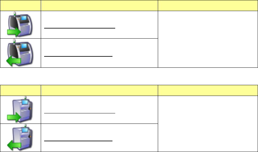
Machine Icon Types
Table 5.8.9-1 Machine icons and their specifications
Icon Setting Applicable machine models
Board transport direction: Left to right
Reference side: Front
・RX-6 series
・RX-7 series
・KE-3020 series
・KE-3020R series
・KE-3010 series
・KE-3020V series
・KE-3020VR series
・FX-3 series
Board transport direction: Right to left
Reference side: Front
Board transport direction: Left to right
Reference side: Rear
Board transport direction: Right to left
Reference side: Rear
Icon Setting Applicable machine models
Board transport direction: Left to right
・RS-1 series
・JM-100
Board transport direction: Right to left
Icon Setting Applicable machine models
Board transport direction: Left to right
・JM-10 series
・JM-20 series
Board transport direction: Right to left
Icon Setting Applicable machine models
Board transport direction: Left to right
・RP-1
Board transport direction: Right to left
JaNets Instruction Manual 5. Shopfloor Setup
5-85
Icon Setting Applicable machine models
Board transport direction: Left to right
・RV-1
Board transport direction: Right to left
Icon Setting Applicable machine models
Board transport direction: Left to right
・RV-2 series
Board transport direction: Right to left