JANETS_INM.pdf - 第226页
JaNets In structio n Manual 7. Program Editor 7- 19 Setting the code parsing data When you se lect the “2 D Cod e (OC C), ” “ Multi - code read, ” “ Back side mul ti - code reader ” and “2 D (ind ivid ual) ” in the 1 D/2…
JaNets Instruction Manual 7. Program Editor
7-18
Table 7.4-7 Items
Item
Contents
Transport offset, auto
The stop position is determined by optimization.
Transport offset, fixed
The stop position is set to an optional position.
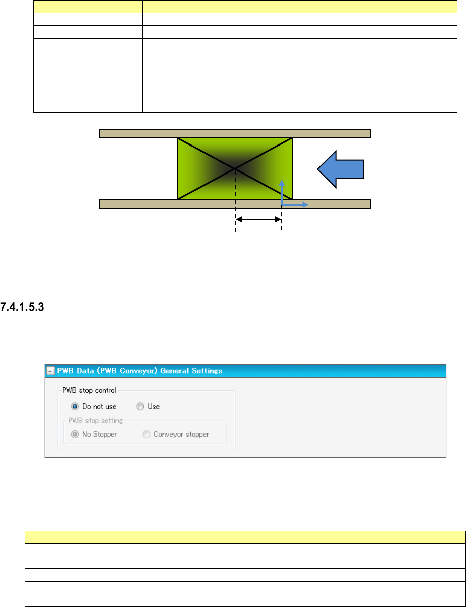
Stop positioning dis-
tance
The PWB stop position is set. For the stop position, the distance from the
reference coordinate origin to the center coordinates of PWB is set. (See
the following figure.)
It is supposed that when the center of PWB exists on the right side of the
reference coordinate origin, a positive value is set, and that when the cen-
ter exists on the left side, a negative value is set.
Figure 7.4-19 Positioning distance
“PWB Conveyor” screen (General Settings)
Only when a machine (RX-6 series) that allows you to select whether a conveyor stopper is to be
used or not is assigned to the production line, this screen appears.
Figure 7.4-20 “PWB Data (PWB Conveyor)” screen (General Settings)
You can specify how to stop a board in the “PWB stop control” column.
Table 7.4-8 Menu items
Item
Contents
PWB stop control Do not use
Operates according to the settings of the machine without mak-
ing any settings in a production program.
PWB stop control Use
Specifies how to stop a board with a production program.
PWB stop setting No Stopper
Stops a board without using any conveyor stopper.
PWB stop setting Conveyor stopper
Stops a board with the conveyor stopper.
Center of PWB
Reference coordinate origin
Positioning distance
JaNets Instruction Manual 7. Program Editor
7-19
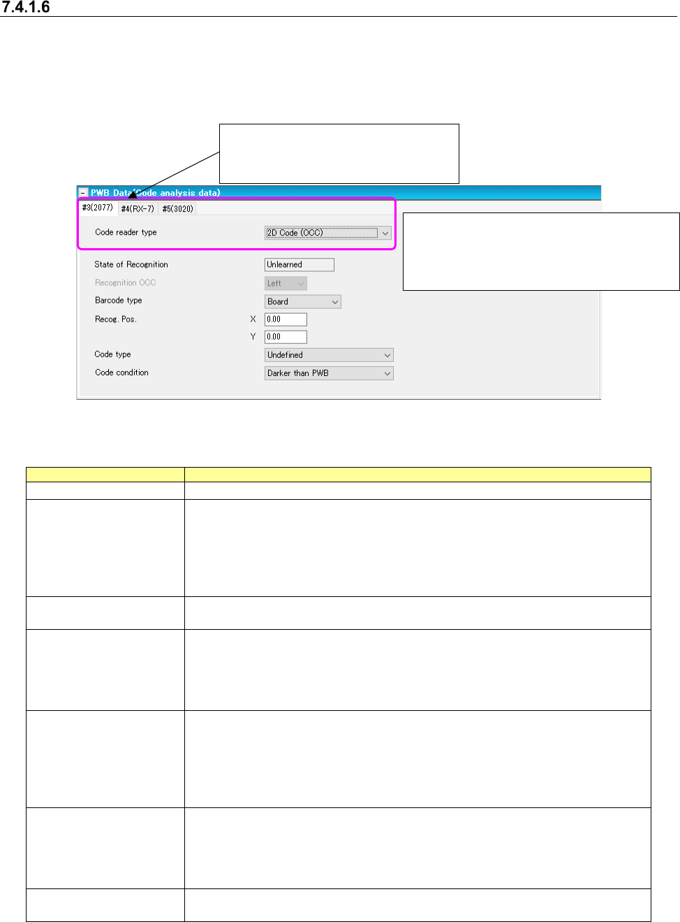
Setting the code parsing data
When you select the “2D Code (OCC),” “Multi-code read,” “Back side multi-code reader” and “2D
(individual)” in the 1D/2D code reader field on the “Basic Settings” screen, the “PWB data (Code
Parsing Data)” screen appears.
In addition, the “Code Parsing Data” is displayed in the tree view of the PWB data.
Figure 7.4-21 “PWB Data (Code Parsing Data)” screen
Table 7.4-9 PWB data (Code analytical data) screen
Items
Description
Code reader type
Specify the code reader type for each machine of the production line.
State of Recognition
Display the learning state of code data.
Only when all the machines which can use the code on a line have
referred to the state of mark recognition learning of code data and learned
it, the “Learned” is displayed.
Except for it, the “Unlearned “is displayed.
This item cannot be changed but be viewed.
Recognition OCC
Select an OCC used for recognition.
This is an unselectable item.
Barcode type
Select between “Board” (default) and “Circuit.”
When selecting “Board," use the barcode stuck on every board.
When selecting "Circuit," use the barcode stuck on every circuit.
When a PWB configuration is a "Matrix circuit" or a "Non-matrix circuit,"
"Circuit" is selectable.
Recog. Pos.
Input the coordinates from a reference point to a center of code.
A reference point changes depending on a barcode type.
When "Board” is selected as a barcode type, the coordinates come from
the board origin.
When "Circuit" is selected as a barcode type, the coordinates come from
the circuit origin.
Code type
Select a code type.
Select from among “Undefined” (default), "DataMatrix", "QR Code",
"Micro QR Code", and "1-D."
Only when a "multi-code reader" is selected in the setting of the
traceability of a basic setup, "1-D" is selectable.
Code condition
Select a code condition.
Select between “Darker than PWB” (default) and Brighter than PWB.”
* If any of the code parsing data is changed,
the “State of Recognition” menu item is set
to “Unlearned,” and the code data is
cleared.
*This menu item is displayed on the
screen only when you select “2D (indi-
vidual)” in the “1D/2D code reader”
JaNets Instruction Manual 7. Program Editor
7-20
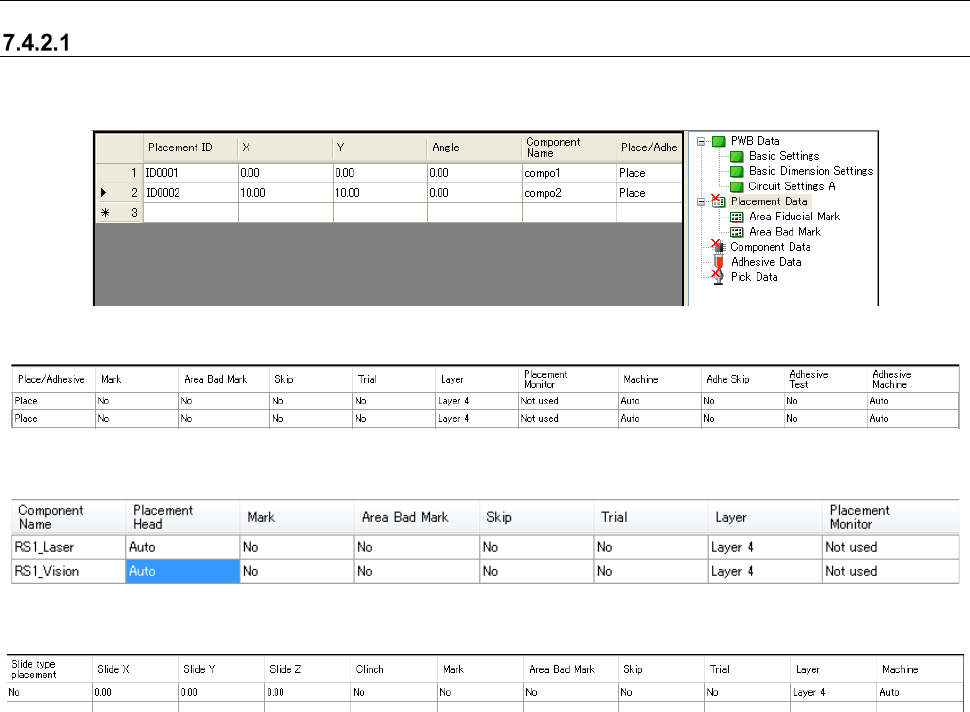
7.4.2 Editing placement data
Placement data
When you select the “Placement Data” from the tree view, the following screen appears.
Figure 7.4-22 “Placement Data” screen 1
Figure 7.4-23 “Placement Data” screen 2 (In the line mode)
Figure 7.4-24 “Placement Data” screen 2 (In the EPU mode)
Figure 7.4-25 “Placement Data” screen 2 (In case of the Line Mode Including JM-100)
[When a production line includes a JM series machine]
None of the menu items, “Place/Adhesive,” “Placement Monitor,” “Adhe Skip,” “Adhesive Test” and
“Adhesive Machine” are displayed on the screen.
[When the JM series EPU is used]
The menu item “Placement Monitor” is not displayed on the screen.
[In Case of the Line Including JM-100 and EPU of JM-100]
Slide Mounting, Slide XYZ and Clinch Setting are displayed.