JANETS_INM.pdf - 第612页
JaNets In structio n Manual 16 Component D ataba se 16 - 12 Adhesion patter n scr een The adhesio n pattern s creen set s the adhesi on data f or correspon ding comp onent s. It is displ ayed by going to the com pon ent …
JaNets Instruction Manual 16 Component Database
16-11
“Pick Conditions” setting window
The “Pick Conditions” setting window allows you to specify component pick-up conditions
information to be used with the corresponding component.
When you click the <Pick Conditions> button of the item buttons displayed on the component data
edit screen described in Section 16.3.2 “Basic setting screen,” this “Pick Conditions” setting
window appears.
See Section 7.4.3.6 “Pick Conditions General Setting screen” of Chapter 7 for how to edit data on
this window.
“Place Conditions” setting window
The “Place Conditions” setting window allows you to specify component placement conditions
information to be used with the corresponding component.
When you click the <Place Conditions> button of the item buttons displayed on the component
data edit screen described in Section 16.3.2 “Basic setting screen”, this “Place Conditions” setting
window appears.
See Section 7.4.3.7 “Placement conditions general setting screen” of Chapter 7 for how to edit
data on this window.
“Check” setting window
The “Check” setting window allows you to specify check information to be used with the
corresponding component.
When you click the <Check> button of the item buttons displayed on the component data edit
screen described in Section 16.3.2 “Basic setting screen”, this “Check” setting window appears.
See Section 7.4.3.8 “Component check detailed information setting screen” of Chapter 7 for how
to edit data on this window.
“Vision” setting window
The “Vision” setting window allows you to specify recognition information to be applied when the
corresponding component is to be centered with a VCS.
When you click the <Vision> button of the item buttons displayed on the component data edit
screen described in Section 16.3.2 “Basic setting screen”, this “Vision” setting window appears.
See Section 7.4.3.9 “Vision” of Chapter 7 for how to edit data on this window.
Clinch Setting Screen
Clinch Setting Screen sets the cognitive information in case of performing clinch by the
corresponding component.
It is displayed when clicking “Clinch” button by the item button of component data editing screens
for “16.3.2 Basic setting screen”.
Refer to Chapter 7 “7-4-3-11 Clinch” for the editing method.
JaNets Instruction Manual 16 Component Database
16-12
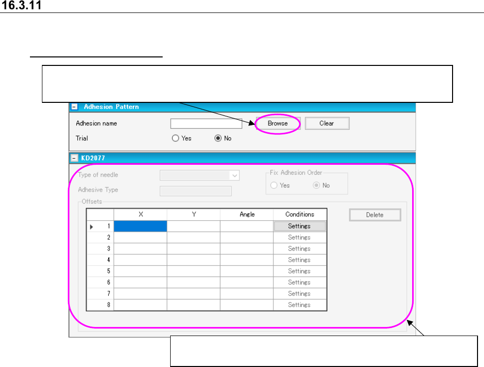
Adhesion pattern screen
The adhesion pattern screen sets the adhesion data for corresponding components. It is displayed
by going to the component data editor screen and clicking on the title bar item [Dispense]. (See
16.3.2 “Basic setting screen”)
Figure 16.3-5 Adhesion pattern screen
Displays a list of adhesion data created on the “Adhesive Pattern” screen.
You can select an adhesion pattern to be applied from the adhesion data list screen.
When you select a pattern, the corresponding adhesion pattern name is displayed on the screen.
When you set the “Adhesion name,” you can edit data displayed here.
See Section 7.4.4.2 “Adhesive data” for how to enter data.
JaNets Instruction Manual 16 Component Database
16-13
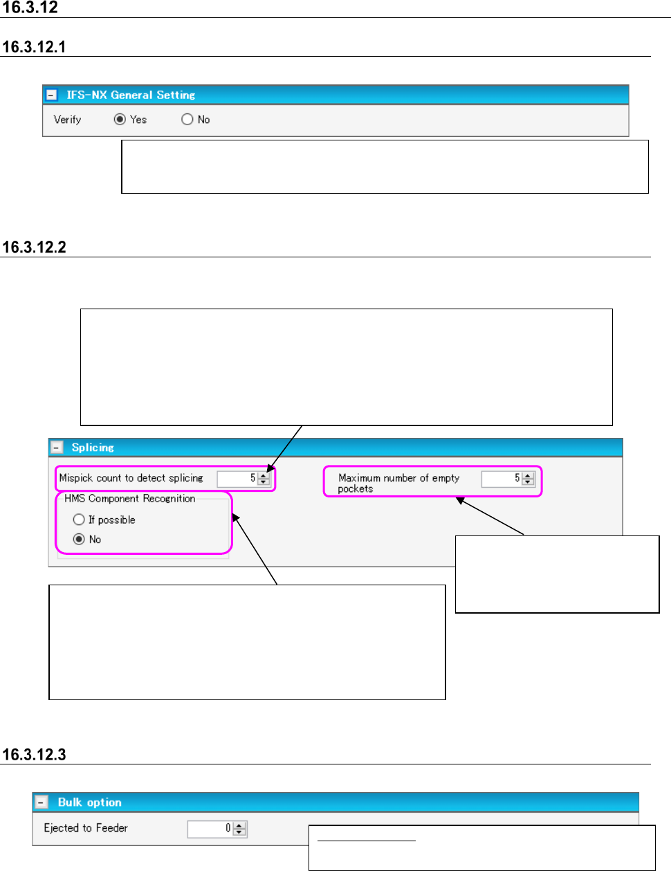
Verify settings
General setting
These are items for the general setting of all currently recorded components.
Figure 16.3-6 IFS General Setting
Splicing settings
This item should be specified when the package style is tape. Note that this item is not applied to
a 32-mm adhesive paper tape.
Figure 16.3-7 Splicing settings
Bulk option
This item only makes settings for bulk components.
Figure 16.3-8 Bulk option
Ejected to Feeder: Enter the number of components
loaded in one bulk.
After the splicing operation, if the pickup error is counted by the same number of times as the
specified number here, the system informs the server that the spliced point has been detected
as the position of changing components.
* Since this setting becomes effective when a component is loaded to the mounter, the
corresponding setting of components already loaded to the mounter is not changed.
Input range: From the number of 1 to 100
Specify whether to inspect the component with the HMS, when the
spliced point is detected by the mispick count.
If possible: Inspects the component if the machine has the HMS.
No: Does not inspect.
* Setting of the “HMS Component Recognition” is applied to
components whose size is equal to that of a 1005 or larger.
This sets whether or not verification takes place at the position where a component is fixed
when verifying with a mounter or verifying outside setup with the setup explorer. Setting [No]
allows production to begin with the mounter even with status unverified.
Input the maximum number of the
space pocket.
Default: 5
Setable range: 1-100