JANETS_INM.pdf - 第318页
JaNets In structio n Manual 7. Program Editor 7- 111 7.5 Descr iption of Each S cree n 7.5.1 Main scr een The entire sc reen o f the Progra m Editor is s hown be low . Figure 7.5 -1 Main scre en When you dra g and drop a…
JaNets Instruction Manual 7. Program Editor
7-110
7.4.7 Editing the station data
This screen allows you to set data such as a production program when a production line includes a
machine other than a mounter or a dispenser.
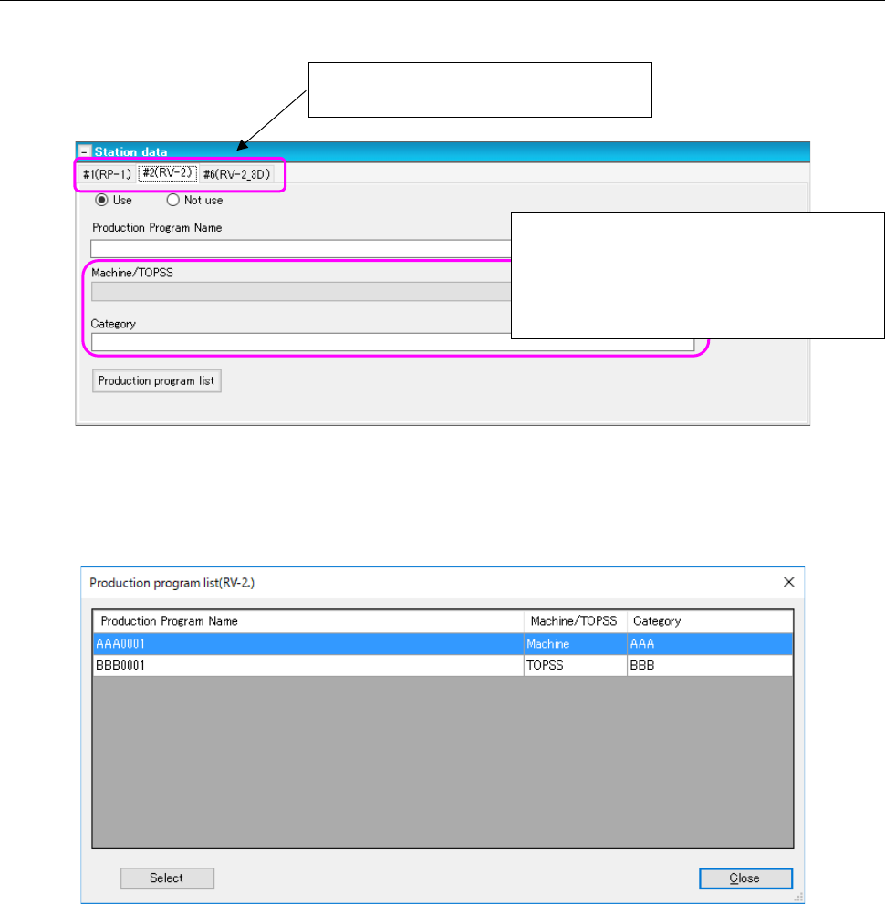
Figure 7.4-151 Station data screen
Specify a production program used with each machine.
When you press the <Production program list> button, the system inquires of the machine for the pro-
duction program list, and then displays the “Production program list” on the screen.
Figure 7.4-152 Production program list screen
After selecting a production program to be used, press the <Select> button. The selected production
program is reflected in the station data.
Set data for each inspection machine
and/or printer of a production line.
When the machine model is an RV-1, RV-2 or
RV-2-3D, specify the distinction of a machine
and TOPSS, and the corresponding category
here. These fields do not appear on the
screen in case of a printer.
JaNets Instruction Manual 7. Program Editor
7-111
7.5 Description of Each Screen
7.5.1 Main screen
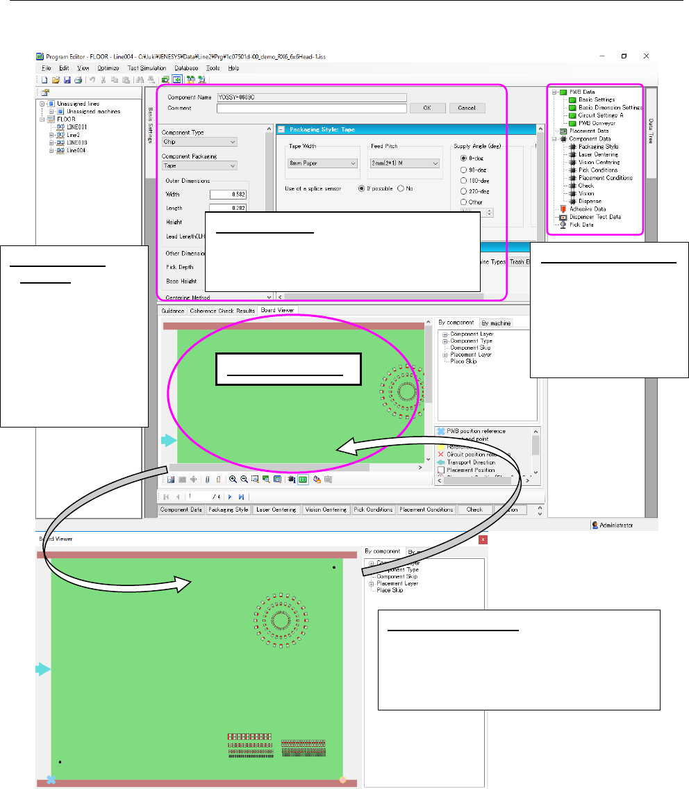
The entire screen of the Program Editor is shown below.
Figure 7.5-1 Main screen
When you drag and drop a production program onto the Board Viewer, the system displays the
corresponding production program.
Separate Board
Viewer: When you
click the right button
of a mouse on the
“Board Viewer,” the
pop-up menu ap-
pears. Select the
[Separate Board
Viewer] command on
this menu.
Viewer display area
Tree view display area:
When you select
each item, the cor-
responding input
screen is displayed
on the data input
area.
Data input area:
Allows you to check or set
items of a production program such as
PWB data, Placement data, Component
data and Pick data.
Return Board Viewer:
Click the right button of
a mouse on the “Board Viewer” to display
the pop-up menu. Select the [Return Board
Viewer] command on this menu to display
the Program Editor screen again.
JaNets Instruction Manual 7. Program Editor
7-112
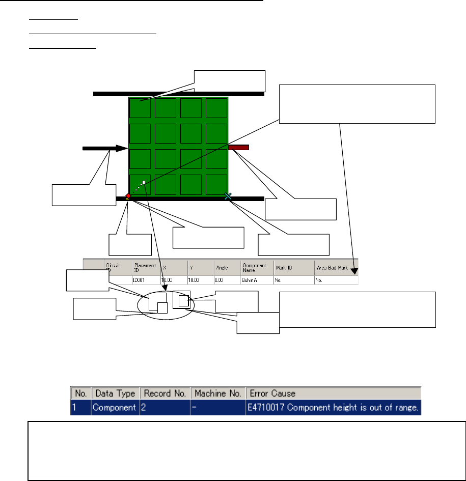
About the tabs displayed on the viewer display area
Guidance: Displays the description of the item selected at the present.
Coherence Check Results: Displays the results of the data coherence check.
Board Viewer: Allows you to check the board transport direction, board layout offset, positioning
hole position, component assignment and so on with showing the image of a board.
When you double-click the desired component, the system selects its Placement data and dis-
plays it on the screen.
Figure 7.5-2 Description of each item displayed on the Board Viewer
Circuit assignment
Board transport
direction
Hole
position
Component
A
Component
B
Component
C
Component
D
The system draws a component whose size is
smaller than those of others over them so that
you can understand how components are over-
lapped.
PWB reference posi-
tion
Layout end point
Stopper pin
When you double-click the displayed com-
ponent, its Placement data is displayed.
When you double-click the desired line, the cursor moves to the “Height” cell of the outer di-
mensions of the corresponding Component data. The system also displays the data coher-
ence error message.
When you double-click the error message, the cursor moves to the item that caused the error.