00191025-01.pdf - 第196页
7 Vision Systems SIPLACE 80S /F/G User’s Manual 7.1 Survey of the Vision Systems of the SIPLACE 80 S/F/G Machines Ed ition 07/97 from Software Version SR.010.xx 7 - 4 Line engine er The range o f compone nts for opti cal…
SIPLACE 80S/F/G User’s Manual 7 Vision Systems
Edition 07/97 from Software Version SR.010.xx 7.1 Survey of the Vision Systems of the SIPLACE 80 S/F/G Machines
Line engineer 7 - 3
7.1 Survey of the Vision Systems of the SIPLACE 80 S/
F/G Machines
As components become smaller and smaller in size, the lead interconnection and insertion densities increase
and printed-circuit board architectures become more and more complex, the quality demands on the place-
ment accuracy of the machines continue to rise. To cope with these tasks the SIPLACE 80 S/F placement
machines are equipped with optical recognition systems (vision systems) both for centering the boards (PCB
vision system) and also for centering the components (component vision system). The SIPLACE G adhesive
application machine is equipped with a PCB vision system for centering the printed-circuit boards.
7.1.1 Vision Systems in the SIPLACE 80S Placement Machine
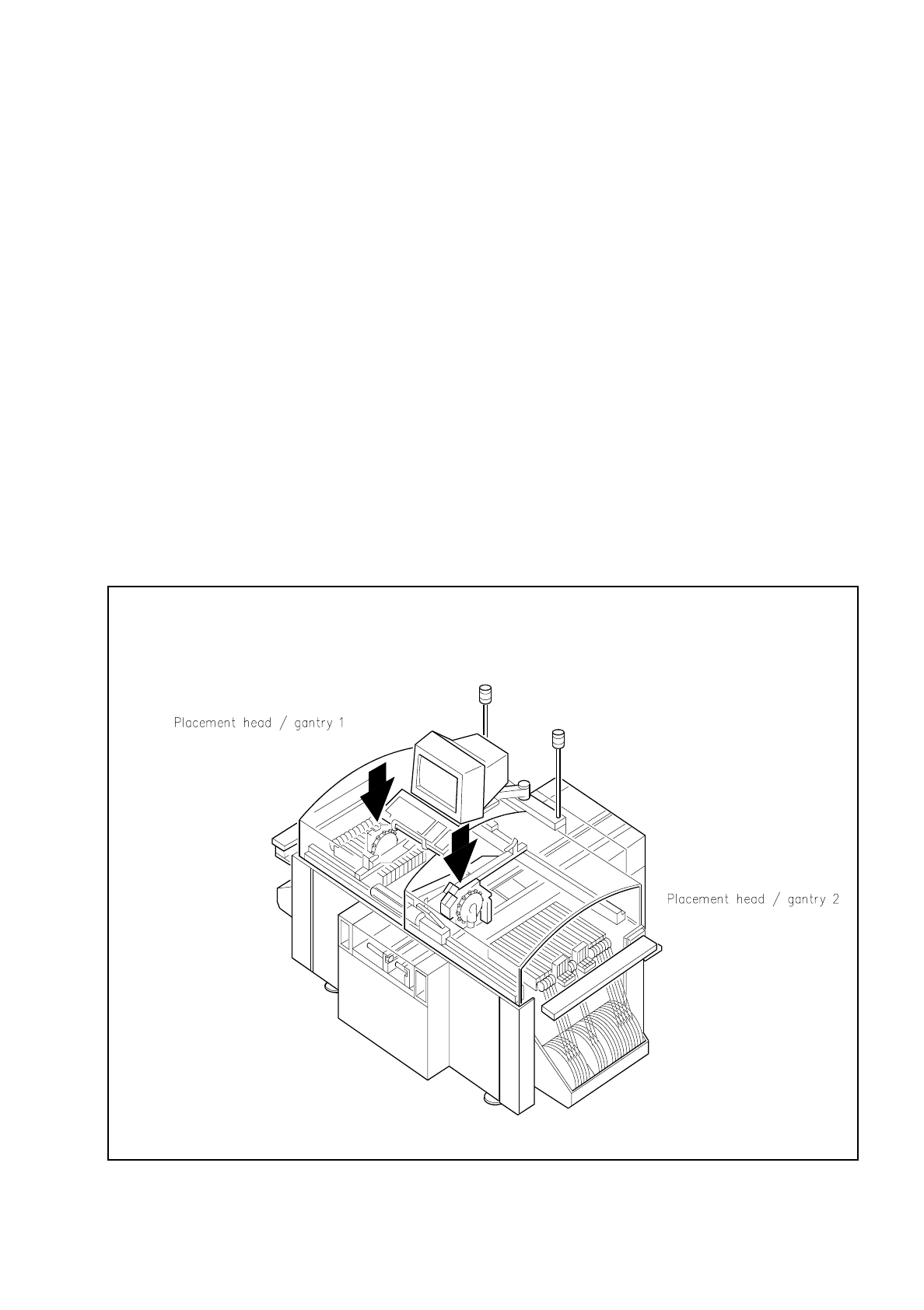
In the SIPLACE 80 S machine with its double gantry system and its two revolver placement heads each place-
ment head is equipped with one CCD camera system for PCB and another for component position recognition
(see Figures 7.1.1 and 7.1.2).
Fig. 7.1.1 Location of the revolver placement heads on the SIPLACE 80S placement system
7 Vision Systems SIPLACE 80S/F/G User’s Manual
7.1 Survey of the Vision Systems of the SIPLACE 80 S/F/G Machines Edition 07/97 from Software Version SR.010.xx
7 - 4 Line engineer
The range of components for optical centering and placement extends from 0402 to SO28 components,
that is, the component size varies between 1.0 mm x 0.5 mm and max. 14 mm x 18 mm with a component
thickness of between 0.3 mm and 4.5 mm.
The PCB vision system for the 80S, 80F and G machines centers boards from the smallest size of 50 mm x 50
mm up to 460 mm x 460 mm, and up to 508 mm x 460 mm (as option). The board thickness may vary here
within the range of 0.5 mm and 3 mm.
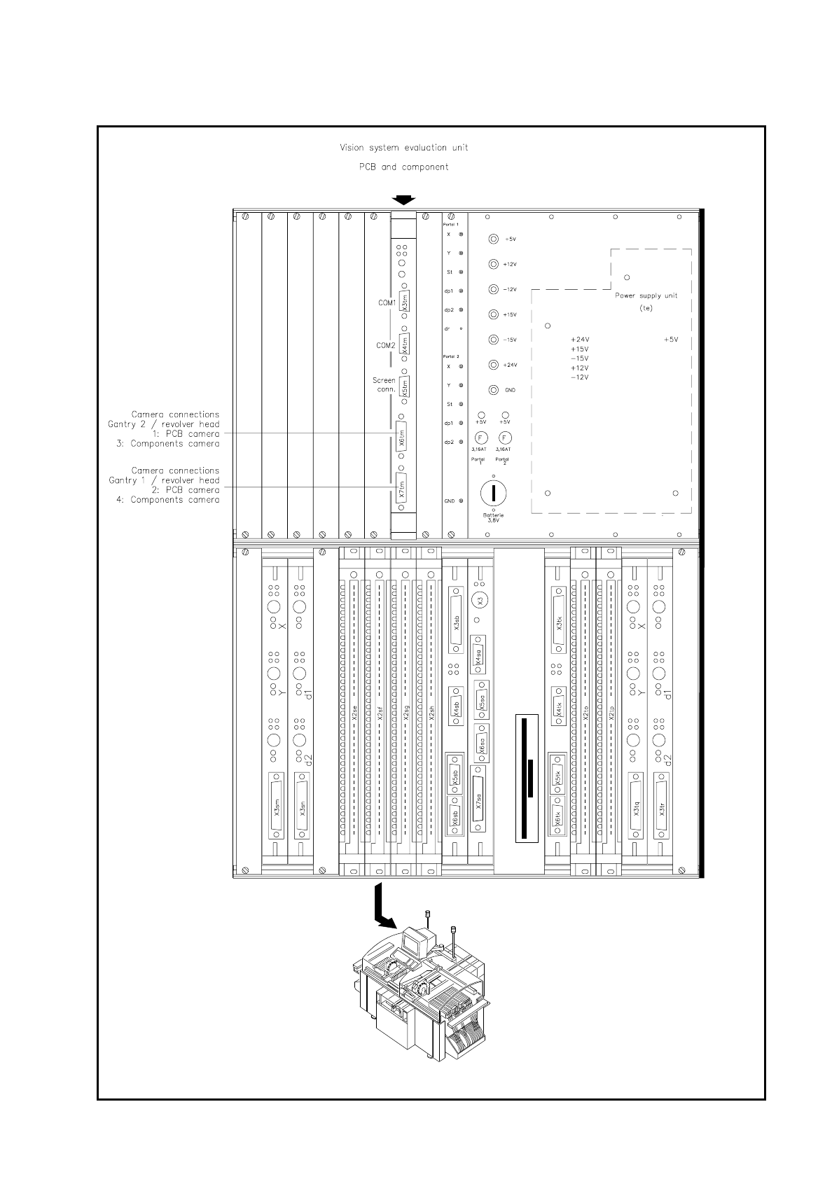
Two vision evaluation units (ICOS MVS systems), accommodated in the control unit of the machine (see Fig.
7.1.3), process and evaluate the signals of the camera systems (PCB and component vision systems) of each
placement head. From the setpoint deviations correction values are determined which, in turn, are used in the
recalculation of the placement positions and angle of rotation of the components which are to be mounted.
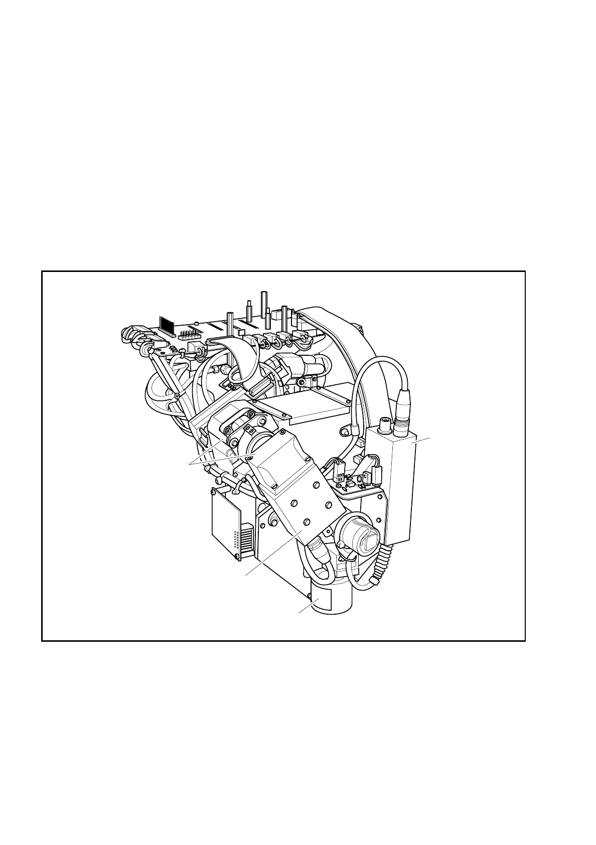
Fig. 7.1.2 Camera systems for PCB and component position recognition on the revolver placement heads
Component camera
PCB optical system
PCB
camera
Deflection mirror and
component optical system
SIPLACE 80S/F/G User’s Manual 7 Vision Systems
Edition 07/97 from Software Version SR.010.xx 7.1 Survey of the Vision Systems of the SIPLACE 80 S/F/G Machines
Line engineer 7 - 5
Fig. 7.1.3 Evaluation units for gantry 1 and gantry 2 of the SIPLACE 80S placement systems