00191025-01.pdf - 第299页
SIPLACE 80S/F/G User’s Manual 7 Vision Systems Edition 07/97 from S oftware Version SR.010.xx 7.7 Guidelines for Describing P ackage Forms Line engi neer 7 - 107 Fig. 7.7.8 Illumination parameters of other components at …
7 Vision Systems SIPLACE 80S/F/G User’s Manual
7.7 Guidelines for Describing Package Forms Edition 07/97 from Software Version SR.010.xx
7 - 106 Line engineer
7.7.6.3 Settings for Illuminating Standard Components
The standard range of components includes chips (0402 to 2220), tantalum capacitors, Melf components,
PLCCs, QFPs, SOs, SOJs, TSOPs, ICs, and power components.
For the components which are listed below the GF interpreter in the station computer uses the default illumi-
nation parameters listed in Fig. 7.7.7:
–
Chips (0402 to 2220)
–
Tantalum capacitors (component bodies, non-reflective)
–
Melf
–
PLCC, QFP, SO, SOJ, TSOP, ICs
As a rule you will not need to change the illumination parameters for the standard components. For all other
components you will need to determine the illumination values and test them (see Section 7.7.6.4,
Page 7 - 106).
Fig. 7.7.7 Illumination parameters for standard components at the revolver head camera 19 x 25
7.7.6.4 Settings for Illuminating Other Components
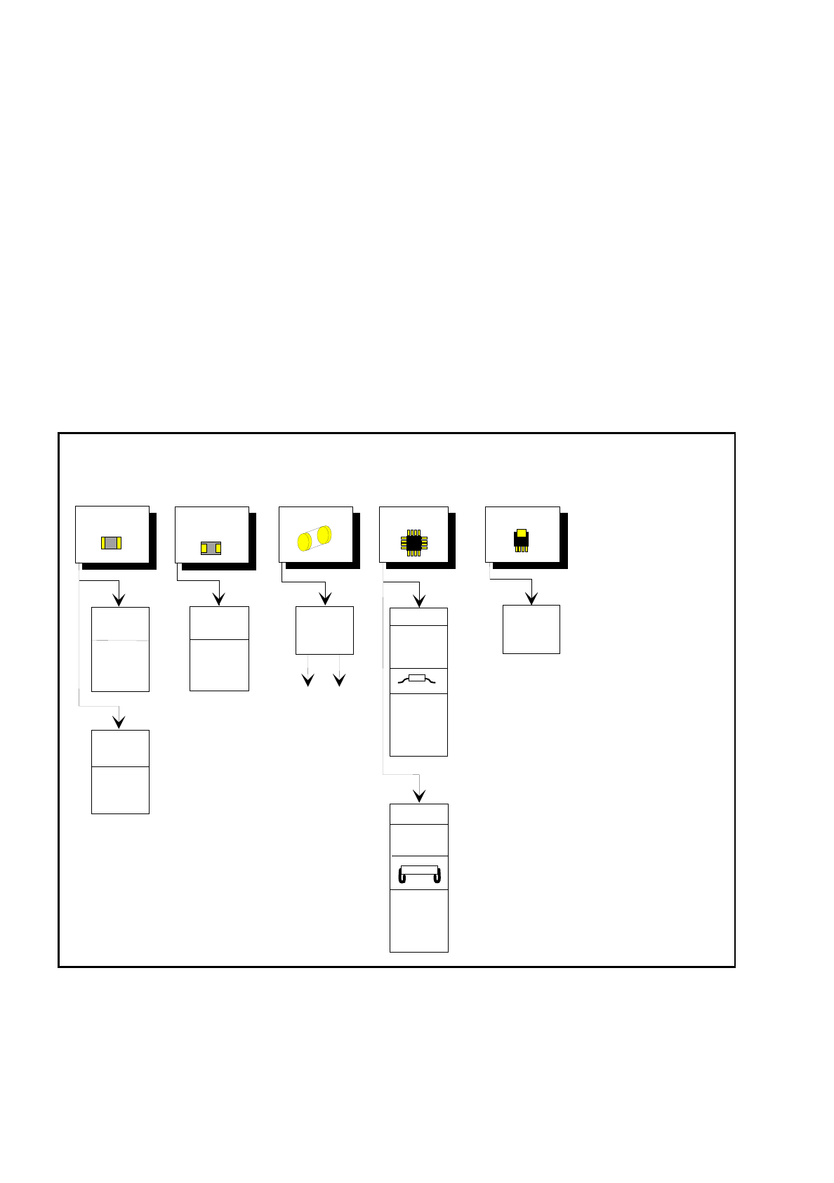
Fig. 7.7.8 presents a list of the illumination settings for other components.
Diagram for adjusting the illumination of standard components
Chip
IC
Power IC
Melf
Tantalum
capacitor
0805 and
larger
0402,
0603
General
flat: 110
steep: 110
flat: 200
steep: 50
flat: 225
steep: 90
flat: 110
steep: 70
Gullwing
SO, SOT,
TSOP
QFP,
flat: 120
steep: 180
flat: 120
steep: 180
J-Lead
PLCC
flat: 140
steep: 90
Illumination
level
Brightness

SIPLACE 80S/F/G User’s Manual 7 Vision Systems
Edition 07/97 from Software Version SR.010.xx 7.7 Guidelines for Describing Package Forms
Line engineer 7 - 107
Fig. 7.7.8 Illumination parameters of other components at the revolver head camera 19 x 25
Adjusting the illumination of other components
Light and dull body
( white, yellow, red, brown, grey,
metallic dull )
Light Ceramic body
Dark and dull body
( black, blue, green )
Reflective body
(independently of color and material)
Dull leads
flat: 180
steep: 180
Visual separation between leads
and body is not possible.
Illuminate body and leads equally.
Measure outline.
Shiny leads
Dull leads
Shiny leads
Clear separation
between leads
and body.
flat: 180 - 255
steep: 0 - 50*
Clear separation between
leads and body.
( applies to dull leads only )
Clear separation
between leads
and body.
J-Lead (PLCC), convex-type leads
Gullwing leads ( SO, QFP )
Dull leads
Shiny leads
flat: 120
steep: 150
flat: 120
steep: 180
Clear separation between body
and leads, if these are convex-
type. In the case of flat leads, will
depend on type, not recommended.
Clear separation
between leads
and body.
J-Lead ( PLCC ), convex-type leads
Gullwing leads ( SO, QFP)
flat: 120
steep: 180
flat: 140
steep: 90
Clear separation
between leads
and body.
Clear separation
between leads
and body.
Other lead shapes
Dull leads
Visual separation between leads
and body is not generally possible.
Shiny leads
Leads:
Outline:
Measuring method:
Visual separation between leads
and body is not possible.
Illuminate body and leads equally.
Measure outline.
flat: 120
steep: 180
Leads are outside the body.
Visual separation between leads
and body is not possible.
Measure outline or leads using
Center
me asuring mode.
J-Lead ( PLCC ), convex-type leads
Gullwing leads ( SO, QFP )
Other lead shapes
Convex-type leads
Other lead shapes
flat: 180
steep: 80 - 140
Visual separation between leads
and body is not generally possible.
Illuminate body and leads equally.
Measure outline.
flat: 120
steep: 180
Visual separation between leads
and body is not generally possible.
Center over body. In general not
recommended.
flat: 180
steep: 0
flat: 0
steep: 180
flat: 180
steep: 180
Measure outline.
Useful measurement is only pos-
sible when the leads are located
within the body.
flat: 180
steep: 180
* Only permissable
when the unevenness
of the body is no more
than 2°.
flat: 180
steep: 0 - 50*
Only possible with
convex-type leads.
flat: 150 - 255
steep: 0 - 50*
flat: 150 - 255
steep: 0 - 50*
Illumination level Brightness

7 Vision Systems SIPLACE 80S/F/G User’s Manual
7.7 Guidelines for Describing Package Forms Edition 07/97 from Software Version SR.010.xx
7 - 108 Line engineer
7.7.6.5 Testing Illumination Settings
You can set the illumination parameters by calling the 'Illumination' option (see Section 7.6.4.4, Page 7 - 92).
Using the Option “Measure component” you can then measure the component and check your settings with
the aid of the measurement results.
Proceed as follows to test your illumination setting:
●
Using the illumination values suggested in Figures 7.7.7 or 7.7.8 carry out measurement.
Measurement should run through successfully.
●
For each level reduce the set brightness level by 50%.
Measurement should run through successfully.
●
For each level raise the set brightness level by 50%.
Measurement should run through successfully.
If you are not successful with the above procedure, proceed as follows:
●
Starting with the suggested illumination value, increase the brightness of each individual illumination level
for as long as measurement is still successful.
●
Find this upper limit value for each individual illumination level in turn.
●
Starting with the suggested illumination value, decrease the brightness of each individual illumination level
for as long as measurement is still successful. Find this lower limit value for each individual illumination
level in turn.
●
Determine the average value of the upper and lower limit values. This will be the optimum illumination
value.
Example of an illumination test:
–
Settings from the diagram:
flat: 170
steep: 120
–
Measure the component. Measurement is successful.
–
Reduce setting values by 50 %.
flat: 85
steep: 60
–
Increase setting values by 50 %.
flat: 255
steep: 180
–
Measure the component. Measurement is successful.
–
Reset the settings to the suggested values:
flat: 170
steep: 120
➧
optimum setting