00191025-01.pdf - 第437页
9 Maintenance SIPLACE 80S /F/G User’s Manual 9.6 IC Head (SIPLACE 80F) Edition 07/97 from Software Version SR.010.xx 9 - 78 9.6. 4.1 Replaci ng the Silencer NOTE Contaminat ion of t he filter in the sile ncer ma y lead t…
SIPLACE 80S/F/G User’s Manual 9 Maintenance
Edition 07/97 from Software Version SR.010.xx 9.6 IC Head (SIPLACE 80F)
9 - 77
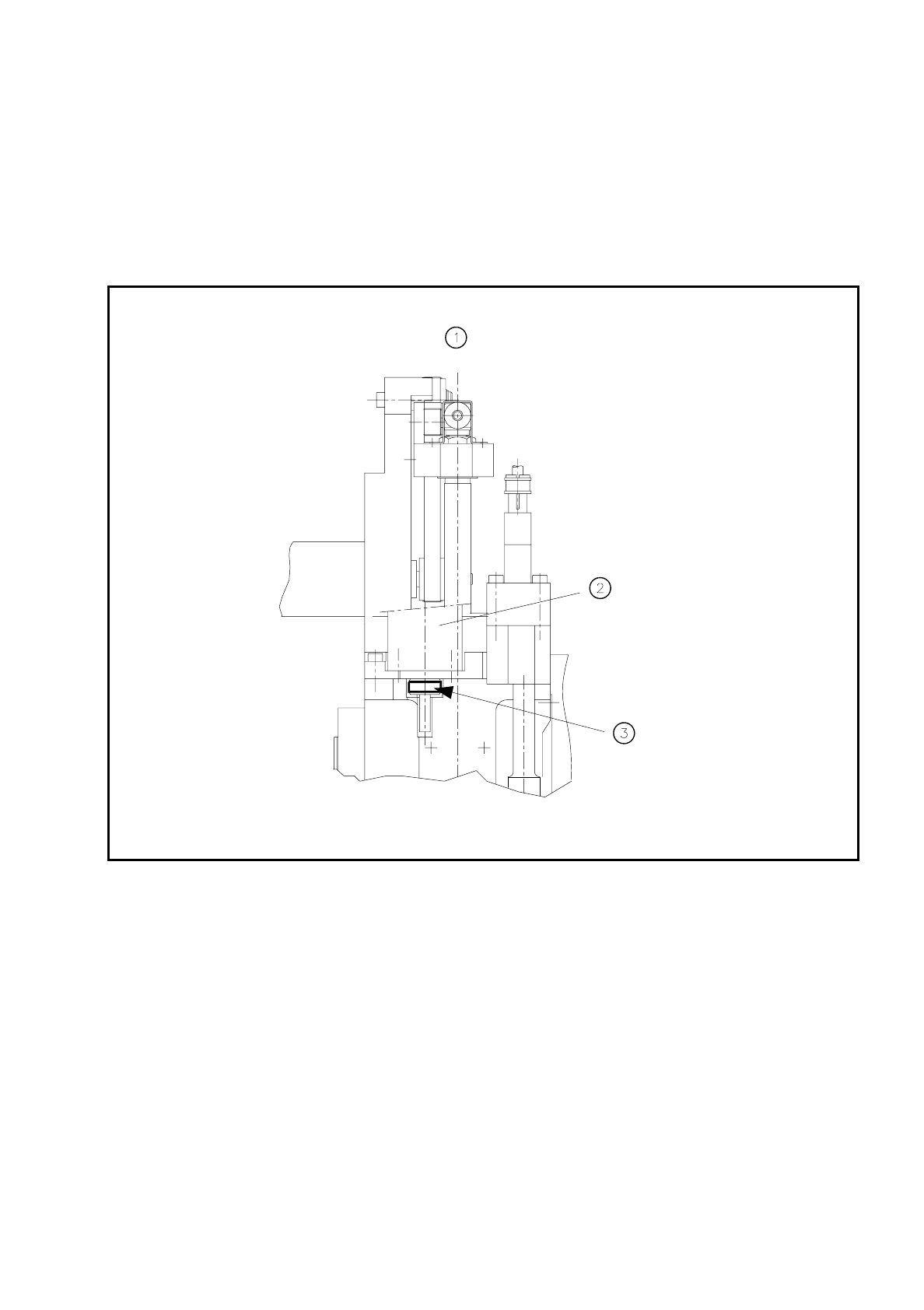
9.6.4 Cleaning the Friction ring of the D Drive Unit
●
Move the IC head to the service position.
●
Remove the protective panel (2 M3 hexagon socket screws).
●
Clean the visible area at the circumference of the friction ring (see Fig. 9.6.4) with alcohol and a clean
cloth.
Fig. 9.6.4 Cleaning the friction ring of the d drive unit
Key to
Fig. 9.6.4
1 View of the IC head in the direction of PCB transport
2 D axis motor
3 Use alcohol to clean the circumference of the friction ring.
●
Switch the machine on and rotate the d axis as described below:
Hold the cloth dampened with alcohol against the circumference of the friction ring:
Select the
IC head
menu in the
Gantry 1 functions
menu and click on the
Turn D axis
button.
(Each time you click on this option the axis will make a quarter-turn. )
Clean in this way the entire circumference of the friction wheel.
9 Maintenance SIPLACE 80S/F/G User’s Manual
9.6 IC Head (SIPLACE 80F) Edition 07/97 from Software Version SR.010.xx
9 - 78
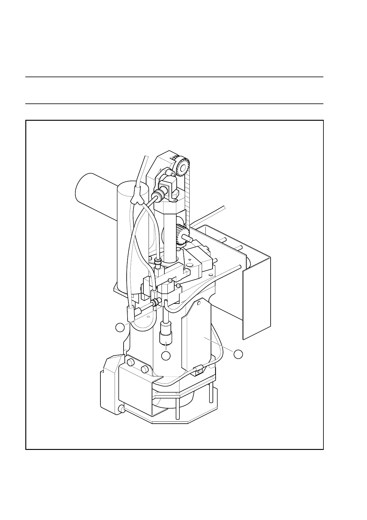
9.6.4.1 Replacing the Silencer
NOTE
Contamination of the filter in the silencer may lead to faults in the vacuum generation unit.
Fig. 9.6.5 Replacing the silencer filter of the vacuum generator
Spare part
Silencer G-1/8 CV05 HS, Item No. 00308498-01
2
3
1

SIPLACE 80S/F/G User’s Manual 9 Maintenance
Edition 07/97 from Software Version SR.010.xx 9.6 IC Head (SIPLACE 80F)
9 - 79
Key to
Fig. 9.6.5
1 IC head
2 Silencer cap
3 Vacuum generator
Sequence of work in
Fig. 9.6.5
A Viewed in the IC head mounting direction
●
Move the IC head to the service position.
DANGER
∆
!
∆
!
∆
!
Switch the automatic placement system off at the main switch and disconnect from the power supply.
●
Remove the cover over the compressed air unit in the machine base. To do so, use a size 3 socket-head
screwdriver to remove the two hexagon socket screws.
●
In addition, turn off the compressed air supply at the shut-off cock in the compr. air unit (see Fig. 9.3.5).
●
Unscrew and remove the silencer.
●
Place the new silencer in position and screw it down.
9.6.5 Cleaning the Vacuum Nozzle and O-Rings, Checking and Greas-
ing the O-Rings
NOTE
Contamination of the vacuum nozzle may lead to vacuum faults.
●
Check whether the compressed air specifications have been complied with, if necessary carry out mainte-
nance of the compressed air unit.
Spare parts:
1 o-ring, 5 x 1.5 NBR 70B, Item No. 00305480-01
1 o-ring, 8 x 1.0 NBR 70B, Item No. 00201179-01
9.6.5.1 Preparatory Work
The IC head is in the service position, the machine is switched off at the main switch, the compressed air is
also switched off at the stop valve of the compressed air unit.
●
Remove the vacuum nozzle. The sequence of work is shown in Fig. 9.6.6 and the following key.
9.6.5.2 Maintenance of the Vacuum Nozzle and O-Rings
●
Remove the o-rings and the sleeve from the vacuum nozzle and carry out maintenance as shown in Fig.
9.6.7.
●
Re-assemble the parts after maintenance and insert the vacuum nozzle vertically with a slight twist into the
vacuum generator as far as the stop. The o-ring in the annular groove in the nozzle must slide into the hole.