00191025-01.pdf - 第454页
SIPLACE 80S/F/G User’s Manual 9 Maintenance Edition 07/97 from S oftware Version SR.010.xx 9.8 Camera Systems and Coplanarity Laser Module 9 - 95 9.8 Camera Syste ms and Coplana rity Laser Module 9.8.1 PCB Camera System …

9 Maintenance SIPLACE 80S/F/G User’s Manual
9.7 Wafflepack Changer Edition 07/97 from Software Version SR.010.xx
9 - 94

SIPLACE 80S/F/G User’s Manual 9 Maintenance
Edition 07/97 from Software Version SR.010.xx 9.8 Camera Systems and Coplanarity Laser Module
9 - 95
9.8 Camera Systems and Coplanarity Laser Module
9.8.1 PCB Camera System in the SIPLACE 80S, 80F and G
The optical system of the PCB camera system requires no cleaning whatsoever.
9.8.2 Component Camera System at the Revolver Head (SIPLACE 80S
and 80F)
The optical system of the component camera system requires no cleaning whatsoever.
9.8.3 Component Camera Systems for the IC Head (SIPLACE 80F)
The locations of the IC head camera system or FC camera system in the machine base is shown in Fig. 9.8.2.
NOTE
Maintenance work for both camera systems is identical.
9.8.3.1 Cleaning Reflecting Surfaces
●
Switch off the machine before removing the illumination head.
●
Pull the illumination head of the component camera with care vertically upwards and off.
●
Cover the now exposed component camera with a box.
●
Wipe the reflecting interior of the illumination head indicated in Fig. 9.8.1 carefully with an absolutely soft,
dry, lint-free and clean cloth. Use special lens cloth (for example from Kodak) or lens cleaning tissue (also
from Kodak).
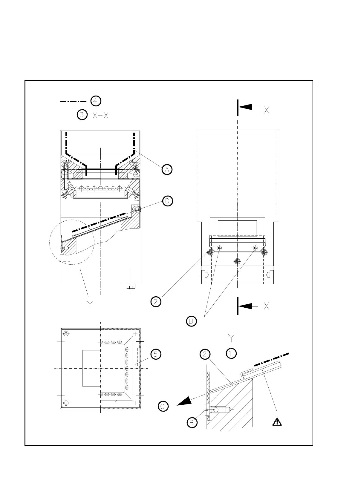
9.8.3.2 Cleaning the Glass Disk
Remove the glass disk for cleaning as follows:
●
The illumination head will already have been removed from the component camera (see 9.8.3.1).
●
Unscrew and remove the M2.5 hexagon socket screws from the glass holder. Pull the glass holder and the
glass disk with care diagonally downwards and out (see Fig. 9.8.1, Page 9 - 96).
●
Clean the glass disk with a clean and dry lens cloth (see above) or lens cleaning tissue.
●
Fit the glass disk back in the reverse sequence and fasten the glass holder.
9 Maintenance SIPLACE 80S/F/G User’s Manual
9.8 Camera Systems and Coplanarity Laser Module Edition 07/97 from Software Version SR.010.xx
9 - 96
●
Place the illumination head back vertically on the component camera so that the fastening of the glass disk
points to the board conveyor. Make sure the illumination head has been pushed on as far as the stop.
Fig. 9.8.1 Cleaning the illumination head of the IC or FC camera