00191025-01.pdf - 第422页
SIPLACE 80S/F/G User’s Manual 9 Maintenance Edition 07/97 from S oftware Version SR.010.xx 9.5 Revolver Head, S egment Version 2 (New N ozzle Seat) 9 - 63 Fig. 9.5.13 Inspection of segment before installation (a segment …

9 Maintenance SIPLACE 80S/F/G User’s Manual
9.5 Revolver Head, Segment Version 2 (New Nozzle Seat) Edition 07/97 from Software Version SR.010.xx
9 - 62
9.5.10.2 Installation of the Segments
For installation of the segments the light gate is fitted to the housing complete (2 hexagon socket screws M3,
see Fig. 9.5.2) and the light gate flap open.
●
Select under "Cycle star". The star position number located at the top in star station 7 is displayed.
●
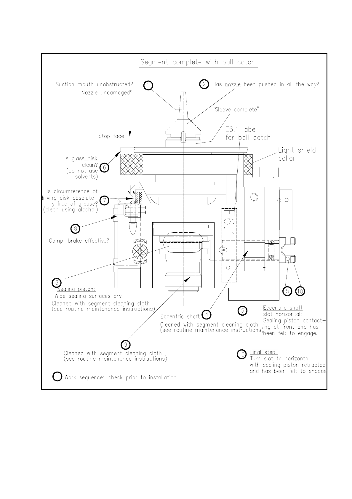
Check with the aid of the following illustration whether all preconditions for installation have been fulfilled
with the segment.
This will help you avoid faults later on in your maintenance work.
NOTE
Pay particular attention to the slot position of the eccentric shaft: it is essential that it is positioned horizon-
tally! An incorrect slot position will lead to a fatal error message as the star cannot be cycled further.
The allocation of segment number/nozzle size and star position number must be reestablished after instal-
lation of the segment.
●
Pick up the correct segment (having noted its allocation) carefully with the correct segment removal tool
(see Fig. 9.5.12). Hold the segment by the segment body, not by the incremental or driving disk (cleaned!).
●
Insert the segment at star station 7 carefully into the star (see Fig. 9.5.12) and press the button at the top
end of the tool. This causes the segment to be set down.
●
With "Cycle star" position the next installation location at the removal station.
●
Insert the next allocated segment in the star. Proceed until all 12 segments have been installed.
●
Continue maintenance work as follows. The placement head will remain in the service position.
●
Select from the menu "Star head"
→
"Vacuum test".
NOTE
When the head function "Vacuum test" is selected the "ACTUAL" nozzle configuration" is displayed on the
screen in the form of a table and beside it - after hitting "Return" in each case - the freshly obtained vac-
uum values in % for each star positioning .
SIPLACE 80S/F/G User’s Manual 9 Maintenance
Edition 07/97 from Software Version SR.010.xx 9.5 Revolver Head, Segment Version 2 (New Nozzle Seat)
9 - 63
Fig. 9.5.13 Inspection of segment before installation (a segment with sealing piston version 2 is shown)
●
With "Return" cycle on to the next segment in the removal station (= star station 7).
●
Look and see whether the nozzle size specified on the screen has been installed.
9 Maintenance SIPLACE 80S/F/G User’s Manual
9.5 Revolver Head, Segment Version 2 (New Nozzle Seat) Edition 07/97 from Software Version SR.010.xx
9 - 64
●
Check the vacuum values determined in each case.
The following vacuum values are displayed on the screen as a percentage for each star position :
Placement circuit: 2 values, nozzle open and closed
Reject circuit: 2 values, nozzle open and closed
NOTE
When nozzle sizes are the same (see the displayed nozzle configuration) approximately the same vacuum
values in % should be obtained. If this is not the case a mistake may have been made during installation of
the sealing piston ( was the O-ring fitted?) or an incorrect nozzle size is still fitted at the star positions in
question (segments mixed up?).
●
If necessary open the protective covers again and insert the mixed-up segments into the correct stern
positions and as a check repeat the above sequence for all 12 star positions.
●
Close the flap of the light gate in the placement head. Closure of the flap means that light reflections during
the component vision process are prevented.
●
Close the protective covers. After the start button is pressed the head reference run is carried out automat-
ically.
●
Next carry out the height reference run: To do so select from the single functions menu "Star head" the
function "Measure nozzle offset".
–
With the subsequent maintenance work on head 2: Return to "Single functions" and select "Gantry 2".
When the gantries are changed the head reference run (without vacuum test and without height refer-
ence run) takes place automatically.
–
After completion of maintenance work on heads 1 and 2: Quit the "Single functions menu". The head
reference run (without vacuum test and without height reference run) is then repeated.
9.5.10.3 Inspecting the Nozzle and O-Ring in the Sleeve
●
Remove the segments from the star as described under "Removal of the segments" .
●
Inspect the nozzle (see Fig. 9.5.13) as follows:
●
Is the suction mouth of the nozzle clogged or damaged?
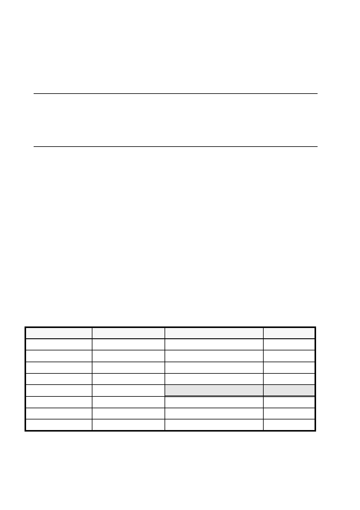
Vectra C130 From item no. Ceramic From item no.
Nozzle type 611 00313996-05 Nozzle type 601 00319483-01
Nozzle type 614 00313997-05 Nozzle type 604 00319484-01
Nozzle type 615 00314000-06 Nozzle type 605 00319485-01
Nozzle type 617 00315267-03
Nozzle type 618 00313993-07
Vectra A700 (EGB) From item no.
Nozzle type 619 00315359-04 Nozzle type 611 00318950-01
Nozzle type 623 00322495-03 Nozzle type 614 00318951-01
Nozzle type 624 00314001-06 Nozzle type 615 00318952-02
Tab. 9.5.2 Revolver head nozzles