00191025-01.pdf - 第423页
9 Maintenance SIPLACE 80S /F/G User’s Manual 9.5 Revolver Head, Segment Version 2 (New Nozzle Seat) Edition 07/97 from Software Version SR.010.xx 9 - 64 ● Chec k the vacu um val ues det ermine d in ea ch case. The foll o…
SIPLACE 80S/F/G User’s Manual 9 Maintenance
Edition 07/97 from Software Version SR.010.xx 9.5 Revolver Head, Segment Version 2 (New Nozzle Seat)
9 - 63
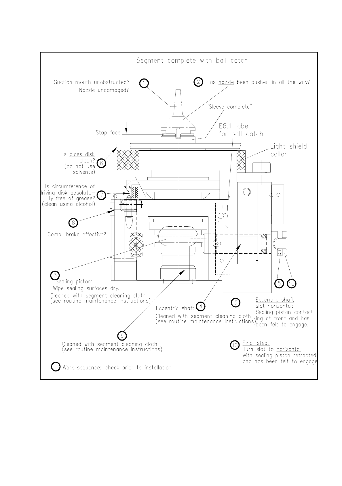
Fig. 9.5.13 Inspection of segment before installation (a segment with sealing piston version 2 is shown)
●
With "Return" cycle on to the next segment in the removal station (= star station 7).
●
Look and see whether the nozzle size specified on the screen has been installed.
9 Maintenance SIPLACE 80S/F/G User’s Manual
9.5 Revolver Head, Segment Version 2 (New Nozzle Seat) Edition 07/97 from Software Version SR.010.xx
9 - 64
●
Check the vacuum values determined in each case.
The following vacuum values are displayed on the screen as a percentage for each star position :
Placement circuit: 2 values, nozzle open and closed
Reject circuit: 2 values, nozzle open and closed
NOTE
When nozzle sizes are the same (see the displayed nozzle configuration) approximately the same vacuum
values in % should be obtained. If this is not the case a mistake may have been made during installation of
the sealing piston ( was the O-ring fitted?) or an incorrect nozzle size is still fitted at the star positions in
question (segments mixed up?).
●
If necessary open the protective covers again and insert the mixed-up segments into the correct stern
positions and as a check repeat the above sequence for all 12 star positions.
●
Close the flap of the light gate in the placement head. Closure of the flap means that light reflections during
the component vision process are prevented.
●
Close the protective covers. After the start button is pressed the head reference run is carried out automat-
ically.
●
Next carry out the height reference run: To do so select from the single functions menu "Star head" the
function "Measure nozzle offset".
–
With the subsequent maintenance work on head 2: Return to "Single functions" and select "Gantry 2".
When the gantries are changed the head reference run (without vacuum test and without height refer-
ence run) takes place automatically.
–
After completion of maintenance work on heads 1 and 2: Quit the "Single functions menu". The head
reference run (without vacuum test and without height reference run) is then repeated.
9.5.10.3 Inspecting the Nozzle and O-Ring in the Sleeve
●
Remove the segments from the star as described under "Removal of the segments" .
●
Inspect the nozzle (see Fig. 9.5.13) as follows:
●
Is the suction mouth of the nozzle clogged or damaged?
Vectra C130 From item no. Ceramic From item no.
Nozzle type 611 00313996-05 Nozzle type 601 00319483-01
Nozzle type 614 00313997-05 Nozzle type 604 00319484-01
Nozzle type 615 00314000-06 Nozzle type 605 00319485-01
Nozzle type 617 00315267-03
Nozzle type 618 00313993-07
Vectra A700 (EGB) From item no.
Nozzle type 619 00315359-04 Nozzle type 611 00318950-01
Nozzle type 623 00322495-03 Nozzle type 614 00318951-01
Nozzle type 624 00314001-06 Nozzle type 615 00318952-02
Tab. 9.5.2 Revolver head nozzles

SIPLACE 80S/F/G User’s Manual 9 Maintenance
Edition 07/97 from Software Version SR.010.xx 9.5 Revolver Head, Segment Version 2 (New Nozzle Seat)
9 - 65
Fig. 9.5.14 Fitting, removal and inspection of the new nozzle (for segment with sleeve and sealing piston version 2)