00191025-01.pdf - 第217页
SIPLACE 80S/F/G User’s Manual 7 Vision Systems Edition 07/97 from S oftware Version SR.010.xx 7. 3 Compo nent Vision System Line engi neer 7 - 25 A compo nent is d esignated as regular wh en the foll owing four c onditio…

7 Vision Systems SIPLACE 80S/F/G User’s Manual
7.3 Component Vision System Edition 07/97 from Software Version SR.010.xx
7 - 24 Line engineer
Position Recognition System for the IC Head for Flip Chips
Camera type: SONY XC75
Number of pixels: Camera 768 (H) x 494 (V)
Image 640 (H) x 484 (V)
Field of view: 12.2 mm x 9.2 mm
Lighting method: Incident-light illumination (red light)
Image processing: approx. 1 sec with standard flip chips
Screen: RGB monitor (VGA mode) 640 x 484 pixels
Range of components recognized: flip chips and fine pitch components up to approx. 15 mm x 15 mm
Minimum ball size: 80
µ
m
Minimum pitch: 0.2 mm
Number of package forms:
≤
2047
7.3.2.3 Description of Functions
Components are optically centered at the revolver placement head, as described in Section 7.3.1.3 for the
80S machine. With the IC head two optical centering systems are available for the optical centering of compo-
nents:
–
the IC sensor for fine-pitch components up to a size of 55 mm x 55 mm and a minimum pitch of 0.4 mm
and for BGAs (ball grid arrays)
–
the FC sensor for flip chips and fine-pitch components up to a size of 15 mm x 15 mm and a minimum pitch
of 0.2 mm
The IC head picks up the components from the flatpack magazines and positions them over the correspond-
ing optical centering system. Staggered rows of LEDs evenly illuminate the component with red light. The dig-
ital image of the component created by the component camera is transmitted to the vision evaluation unit.
Here the image is evaluated in accordance with the component type. The results of evaluation provide infor-
mation on positional deviations, angle of rotation, lead conditions and the quality of the component image.
For BGAs and flip chips new illumination methods and special algorithms for obtaining component parameters
have been developed which enable this new generation of components to be optically centered as well.
Components which cannot be optically centered will be returned to the flatpack magazine by the IC head for
further analysis.
7.3.3 Criteria for the Registration of Components
●
Shape of the components
With the aid of optical component centering both regular and also irregular components can be centered.
The maximum number of leads permitted in the horizontal and in the vertical directions is 99 in each case.
Criteria for regular components
Definition
SIPLACE 80S/F/G User’s Manual 7 Vision Systems
Edition 07/97 from Software Version SR.010.xx 7.3 Component Vision System
Line engineer 7 - 25
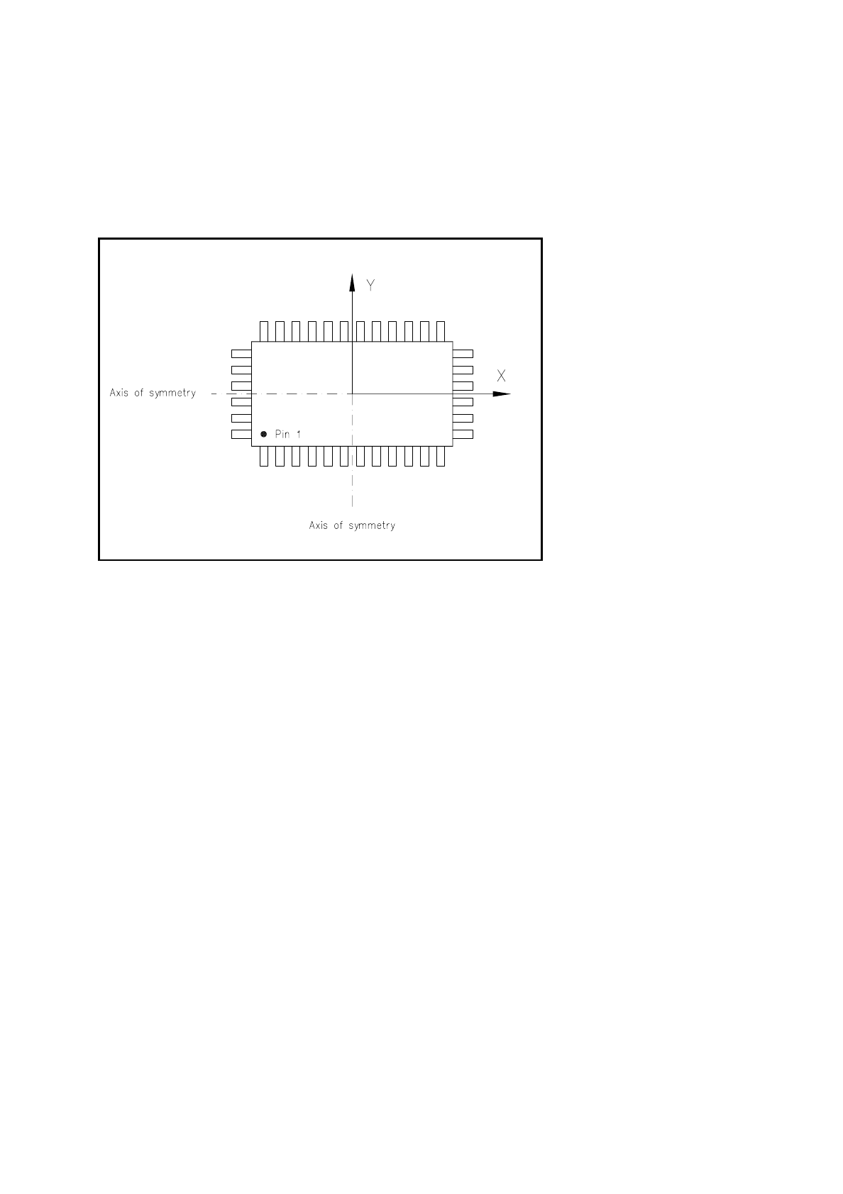
A component is designated as regular when the following four conditions are satisfied:
–
rectangular package form (special case: square shape)
–
only one lead type per side
–
only one lead group per side
–
the lead groups located opposite are in each case symmetrical to the two main axes (x and y axes).
Fig. 7.3.1 Regular component
Criteria for irregular components
Definition
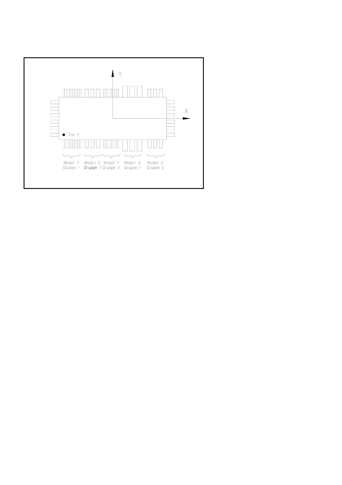
A component is designated as irregular when it does not satisfy the conditions for regular components.
Additional conditions for centering using the component vision system:
–
Up to 3 different lead types are permitted in one row.
–
Up to 15 groups are permitted in one row.
7 Vision Systems SIPLACE 80S/F/G User’s Manual
7.3 Component Vision System Edition 07/97 from Software Version SR.010.xx
7 - 26 Line engineer
Fig. 7.3.2 Example of irregular components
●
Pitch deviation
For each component the pitch deviation (= pitch spacing from lead center to lead center) can be entered sep-
arately in the GF editor. If this value is exceeded, the component will not be centered and therefore not placed.
●
Limit value of quality measurement
The components must not exceed the limit values of quality measurement or else they will not be placed.
Limit values are:
–
Difference in the numbers of leads between the original and the model.
–
Pitch deviation greater than the value in the GF file.
–
Orthogonality defects greater than specified in the GF file.
–
Major deviation in the external dimensions.
–
Deviation of the central point which is greater than the permissible positional tolerance at pick-up.