00191025-01.pdf - 第218页
7 Vision Systems SIPLACE 80S /F/G User’s Manual 7.3 Component Vision System Edition 07/97 from Software Version SR.010.xx 7 - 26 Line engine er Fig. 7.3.2 Example of irregular components ● Pitc h devi ation For each comp…
SIPLACE 80S/F/G User’s Manual 7 Vision Systems
Edition 07/97 from Software Version SR.010.xx 7.3 Component Vision System
Line engineer 7 - 25
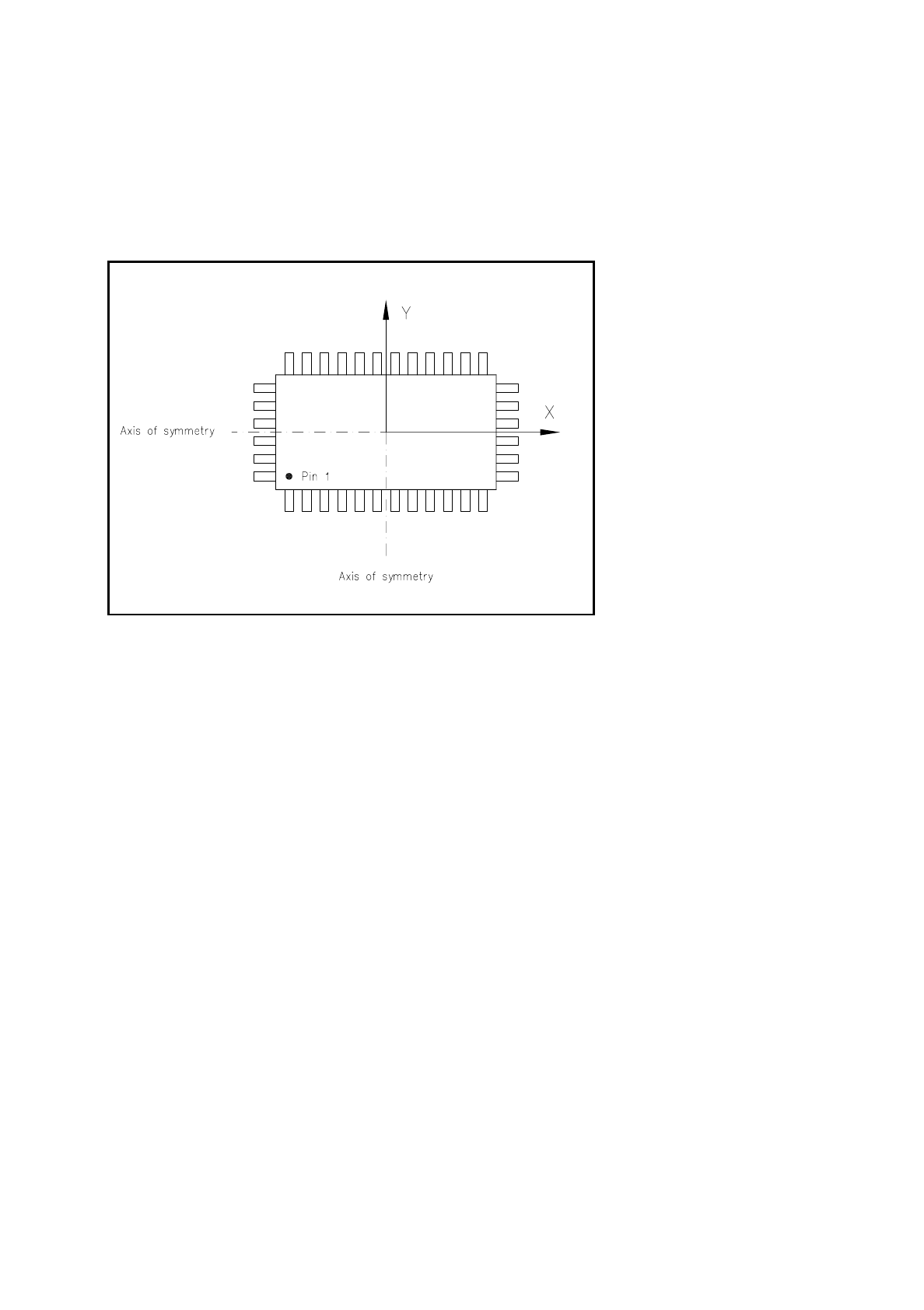
A component is designated as regular when the following four conditions are satisfied:
–
rectangular package form (special case: square shape)
–
only one lead type per side
–
only one lead group per side
–
the lead groups located opposite are in each case symmetrical to the two main axes (x and y axes).
Fig. 7.3.1 Regular component
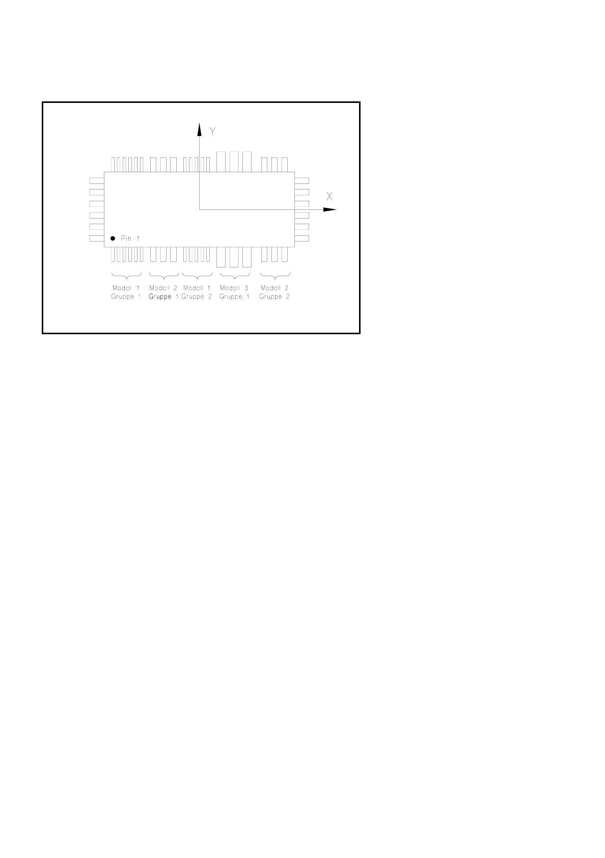
Criteria for irregular components
Definition
A component is designated as irregular when it does not satisfy the conditions for regular components.
Additional conditions for centering using the component vision system:
–
Up to 3 different lead types are permitted in one row.
–
Up to 15 groups are permitted in one row.
7 Vision Systems SIPLACE 80S/F/G User’s Manual
7.3 Component Vision System Edition 07/97 from Software Version SR.010.xx
7 - 26 Line engineer
Fig. 7.3.2 Example of irregular components
●
Pitch deviation
For each component the pitch deviation (= pitch spacing from lead center to lead center) can be entered sep-
arately in the GF editor. If this value is exceeded, the component will not be centered and therefore not placed.
●
Limit value of quality measurement
The components must not exceed the limit values of quality measurement or else they will not be placed.
Limit values are:
–
Difference in the numbers of leads between the original and the model.
–
Pitch deviation greater than the value in the GF file.
–
Orthogonality defects greater than specified in the GF file.
–
Major deviation in the external dimensions.
–
Deviation of the central point which is greater than the permissible positional tolerance at pick-up.
SIPLACE 80S/F/G User’s Manual 7 Vision Systems
Edition 07/97 from Software Version SR.010.xx 7.3 Component Vision System
Line engineer 7 - 27
7.3.4 Safety Information concerning the Component Vision Systems in
the 80F Machine
DANGER
∆
!
∆
!
∆
!
You must not modify or tamper with the safety devices of the 80F machine or of the IC or flip chip module in
any way at all!
The optical radiation of the IC and flip chip sensors corresponds to laser class 1 provided the sensors are per-
manently installed in the machine (EN 60825-1 and IEC 825).
Fig. 7.3.3 Designation of laser class 1
Laser Class 1