00191025-01.pdf - 第541页
11 Station Extensions SIPLACE 80S/F/G User’s M anual 11.3 PCB Bar-Code Edition 07/97 from Software Version S R.010.xx 11 - 16 11.3.4. 1 Adjust ing the Readi ng Beam ● Place th e board onto the input b oard. ● The SR_C ON…

SIPLACE 80S/F/G User’s Manual 11 Station Extensions
Edition 07/97 from Software Version SR.010.xx 11.3 PCB Bar-Code
11 - 15
NOTE
If you know what bar code you want to process during start-up, the bar code will be set to your bar-code type.
Otherwise the CODE 2/5 interleaved bar-code type will be preinstalled. If you want to change your bar-code
type, the steps you will need to take for parametrization are described below.
Parametrization takes place using the program SR_INST_LPBC.001.001.
The only actions you should carry out in the menues are the ones described below. All other parameters are
standard values and need not be changed.
●
Insert the diskette with the SITEST test program into drive A:>
●
Reboot the system using the key combination Strg (Ctrl)+Alt+Entf (Del)
●
Insert the SR_INST_LPBC.001.001 diskette into drive A:>
●
Reboot the system using the key combination Strg (Ctrl)+Alt+Entf (Del)
●
Switch the control system ON.
●
The set-up menu will be opened.
NOTE
If the set-up menu does not open, there is no communication with the PCB bar-code reader.
Possible cause: +24 V power supply missing, interface disconnected, laser defective.
●
In the Set-up menu select < E >
●
In the Code sub-menu select < 1 >
●
In the Code type sub-menu select < 1>
●
Select the code type you want to work with < Customer-specific>
NOTE
When the code type or number of places is changed both new values will need to be keyed in afresh.
●
Key in the number of places in the bar code <Customer-specific>
Confirm with < Enter >
NOTE
Specify a single number for the number of places in the bar code. If you specify a range of numbers, this
may lead to errors.
●
Quit the menu with < Esc >
●
Quit the menu with < Esc >
●
Quit the menu with < Esc >
●
Secure the parameters with "Store permanent" < 3 >
11 Station Extensions SIPLACE 80S/F/G User’s Manual
11.3 PCB Bar-Code Edition 07/97 from Software Version SR.010.xx
11 - 16
11.3.4.1 Adjusting the Reading Beam
●
Place the board onto the input board.
●
The SR_CONF_LPBC.100.001 diskette must still be loaded and the control system be switched on.
●
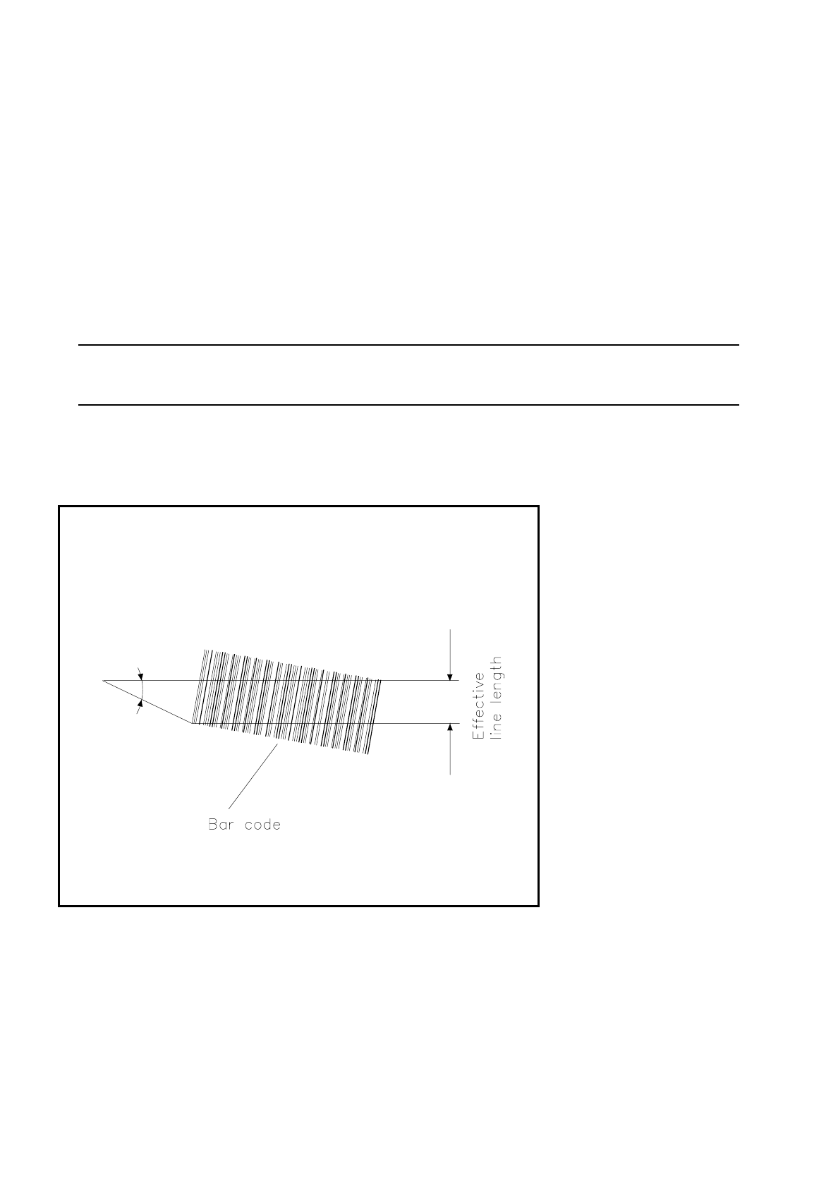
Adjust the reading head so that the laser beam can scan the entire bar code when the board is moved by.
At this point note the reading orientation of the bar code.
●
Switch the read beam ON using the + key on the keyboard.
●
Move the board over the bar-code reader. The bar code which has been read will be displayed on the
screen.
●
Switch the read beam OFF using the -key on the keyboard.
NOTE
For further details on operating and programming, please refer to the UNIX line computer user's manual.
●
Please note,
the smaller the reading angle the larger the effective reading length, and the larger this effective line length
is, the more certain reading of the bar code will be.
Fig. 11.3.2 Reading the bar-code
SIPLACE 80S/F/G User’s Manual 11 Station Extensions
Edition 07/97 from Software Version SR.010.xx 11.3 PCB Bar-Code
11 - 17
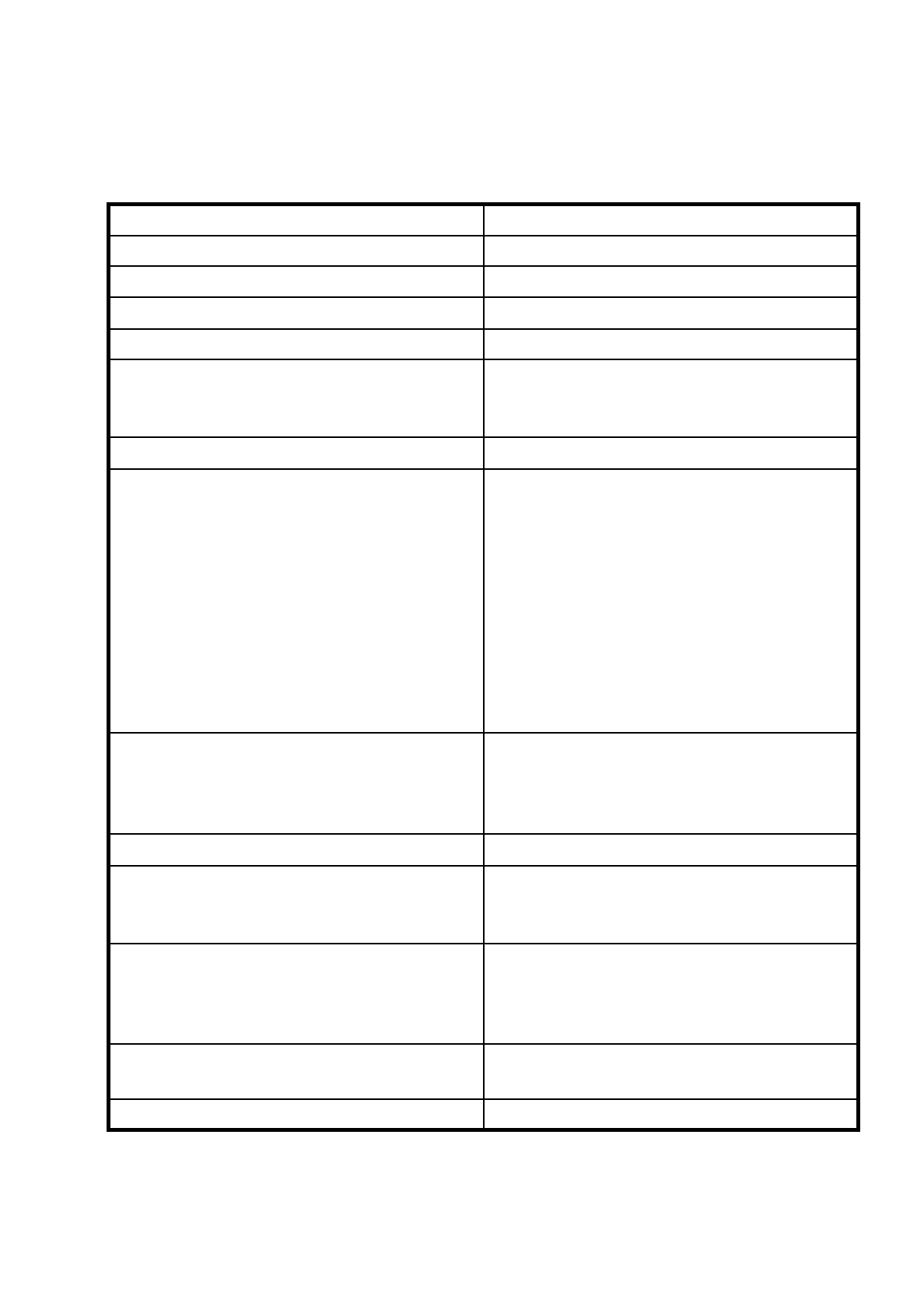
11.3.5 Technical Data
Resolution Finest line thickness 0.19 to 0.3 mm
Reading speed 600 scans/sec.
Reading distance 60 to 90 mm
Reading window 90 mm (max. bar-code length permitted)
Angle of reading head to the bar code 5 to 10°
Light source
Laser diode, 670 nm
1 mW
Laser class 2
Type of protection IP 65
Readable bar-code types
Code 39
Code 128 / EAN 128
Code 2/5 interleaved
Codabar
2/5 IATA
2/5 INDUSTRIAL
UPC
EAN
Pharma code
EAN Addendum
(others available on request)
Line length
≥
4 mm
Requirement: with a board speed of 300 mm/sec
and a scan rate of 600 scans/sec it must be possi-
ble to make 3 readings
Contrast ratio as per DIN 66236
≥
70%
Permitted color of lines
black
dark green
dark blue
Permitted background colors
white
beige
yellow
orange
Bar-code length
(including the two end areas)
≤
90 mm