00191025-01.pdf - 第303页
SIPLACE 80S/F/G User’s Manual 7 Vision Systems Edition 07/97 from S oftware Version SR.010.xx 7.7 Guidelines for Describing P ackage Forms Line engi neer 7 - 111 As a ru le you will not need to change the i llumination p…
7 Vision Systems SIPLACE 80S/F/G User’s Manual
7.7 Guidelines for Describing Package Forms Edition 07/97 from Software Version SR.010.xx
7 - 110 Line engineer
Steep illumination level
The main application for the steep illumination level is for reflective leads, ceramic components and bright
component bodies. It is less suitable for reflective component bodies and BGAs.
NOTE
For the best illumination of most components a combination of these two lighting levels is required.
Using one illumination level will only be successful in exceptional cases.
7.7.7.2 Pseudo-Color Display
The pseudo-color display is used to enable an informative and objective evaluation of the illumination to be
made. Each brightness value is represented by a different color.
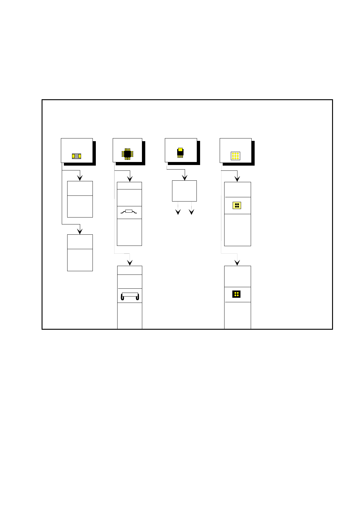
IC head conversion table for the pseudo-color display
For measurement a contrast of at least 4 color steps is required between the leads and the body. Under the
GF manipulator's Illumination menu, components are displayed in pseudo-color on the station computer mon-
itor.
7.7.7.3 Settings for Illuminating Standard Components
The standard range of components includes tantalum capacitors, PLCCs, QFPs, SOs, SOJs, TSOPs, ICs,
power components, and BGAs.
For the components which are listed below the GF interpreter in the station computer uses the default illumi-
nation parameters listed in Fig. 7.7.9:
–
Tantalum capacitors (component bodies, non-reflective)
–
PLCC, QFP, SO, SOJ, TSOP, ICs
–
BGAs (not ceramic BGAs)
Color step Brightness
white light
yellow
orange
red
brown
green
light blue
blue
violet
black dark
SIPLACE 80S/F/G User’s Manual 7 Vision Systems
Edition 07/97 from Software Version SR.010.xx 7.7 Guidelines for Describing Package Forms
Line engineer 7 - 111
As a rule you will not need to change the illumination parameters for the standard components. For all other
components you will need to determine the illumination values and test them (see Section 7.7.7.4,
Page 7 - 111).
Fig. 7.7.9 Illumination parameters for standard components at the IC head camera
7.7.7.4 Settings for Illuminating Other Components
Fig. 7.7.10 presents a list of the illumination settings for other components.
Diagram for adjusting the illumination of standard components
IC
Power IC
BGA
Tantalum
capacitor
BGA
General
flat: 120
middle: 60
steep: 10
Reflective
body
Gullwing
SO, SOT,
TSOP
QFP,
flat: 90
middle: 40
steep: 10
flat: 255
middle: 90
steep: 0
flat: 120
middle: 50
steep: 10
J-Lead
PLCC
flat: 200
middle: 30
steep: 5
Ceramic
BGA
flat: 0
middle: 0-10
steep:80-100
flat: 255
middle: 30
steep: 0
Illumination
level
Brightness
7 Vision Systems SIPLACE 80S/F/G User’s Manual
7.7 Guidelines for Describing Package Forms Edition 07/97 from Software Version SR.010.xx
7 - 112 Line engineer
Fig. 7.7.10 Illumination parameters of other components at the IC-head camera
Adjusting the illumination of other components
Light and dull body
( white, yellow, red, brown, grey,
metallic dull )
Ceramic body
Dark and dull body
( black, blue, green )
Reflective body
(independently of color and material)
Dull leads
flat: 100
middle: 30
steep: 40
Visual separation between leads
and body is not possible.
Illuminate body and leads equally.
Measure outline.
Shiny leads
Clear separation
between leads
and body.
Dull leads
flat: 255
middle: 90
steep: 0
Shiny leads
1. Illuminate body and leads equally.
Measure outline.
2. Trick: Use flat and middle levels to
bring leads image to saturation.
Measure.
Clear separation
between leads
and body.
for variant 2: flat: 150 - 255
middle: 60 - 120
steep: 0
flat: 160
middle: 60
steep: 0
Clear separation
between leads
and body.
Clear separation
between leads
and body.
J-Lead ( PLCC ), convex-type leads
Gullwing leads ( SO, QFP )
Dull leads
Shiny leads
Clear separation
between leads
and body.
Clear separation
between leads
and body.
J-Lead ( PLCC ), convex-type leads
Gullwing leads ( SO, QFP)
flat: 90
middle: 40
steep: 10
flat: 200
middle: 30
steep: 5
Clear separation
between leads
and body.
Clear separation
between leads
and body.
Other lead shapes
Dull leads
Visual separation between leads
and body is not generally possible.
Shiny leads
Leads:
Outline:
Measuring method:
Visual separation between leads
and body is not possible.
Illuminate body and leads equally.
Measure outline.
Visual separation between leads
and body is not possible. Measure
outline or lead tips. Leads are
outside the body.
J-Lead ( PLCC ), convex-type leads
Gullwing leads ( SO, QFP )
Other lead shapes
Convex-type leads
Other lead shapes
Visual separation between leads
and body is not generally possible.
Illuminate body and leads equally.
Measure outline.
Illumination level Brightness
flat: 120 - 140
middle: 40 - 60
steep: 0 - 10
flat: 90
middle: 90
steep: 5 - 10
flat: 90
middle: 40
steep: 10
flat: 200
middle: 30
steep: 5
Visual separation between leads
and body is not generally possible.
Leads:
Outline:
Measuring method:
flat: 120
middle: 40
steep: 10 - 20
flat: 120
middle: 40
steep: 0 - 10
flat: 0
middle: 0
steep: 10 - 20
flat: 0
middle: 0
steep: 20 - 40
flat: 0
middle: 0
steep: 25
flat: 100
middle: 30
steep: 40
flat: 160
middle: 60
steep: 0