00191025-01.pdf - 第281页
SIPLACE 80S/F/G User’s Manual 7 Vision Systems Edition 07/97 from S oftware Version SR.010.xx 7.6 Test Component Line engi neer 7 - 89 ● Parameters of the color im age (5 sectio ns) – 10 parame ters “IN” value s – 10 par…

7 Vision Systems SIPLACE 80S/F/G User’s Manual
7.6 Test Component Edition 07/97 from Software Version SR.010.xx
7 - 88 Line engineer
In this menu you have the possibility of changing
–
the pin dimensions,
–
the package dimensions,
–
the ball image parameter,
–
the illumination parameters, and
–
the transformation table.
●
Pin dimension parameters are
–
optical pin length along the x and y axes of the components
–
optical pin width along the x and y axes of the components
–
spacing of the pins along the x and y axes of the component. By spacing is meant the distance from
the center of one pin to the center of the next pin.
–
Number of pins along the x and y axes of the component
NOTE
The spacing and the pin number can only be altered at the line computer.
●
Package dimension parameters are
–
the external dimensions of the component in millimeters along the x and y axes. By external dimen-
sions is meant the optical dimensions of the component including pin dimensions.
The geometric dimensions of pins and component are stored in the line computer in the GF file. Depending
on the geometry of the component and the illumination by the component camera image defects may
occur. The image does not reproduce the real geometric dimensions - the image is reduced. This is termed
imaging reduction. Thus one refers to the optical dimensions of pin and component. The reduction factor
for every pin dimension / package form is entered in the GF file in the line computer and can be changed
using this menu.
As regards the position definition of the coordinate axes and the definition of regular or irregular components,
please refer to Section 7.3.3.
●
Ball image parameters are
–
internal, external radius type
–
internal, external radius
–
contrast
–
ball model
●
Illumination parameters are
–
the contrast in the image
–
the selection of the top or bottom LED row for steep or shallow-angled illumination of the component
(brightness control).
SIPLACE 80S/F/G User’s Manual 7 Vision Systems
Edition 07/97 from Software Version SR.010.xx 7.6 Test Component
Line engineer 7 - 89
●
Parameters of the color image (5 sections)
–
10 parameters “IN” values
–
10 parameters “OUT” values
The parameters are stored in the GF file in the line computer. When requested, the GF file is sent to the sta-
tion computer. It is then converted and transferred to the MVS computer.
If you change a parameter, it will be entered in the GF file, the GF file converted and then loaded into the MVS
computer.
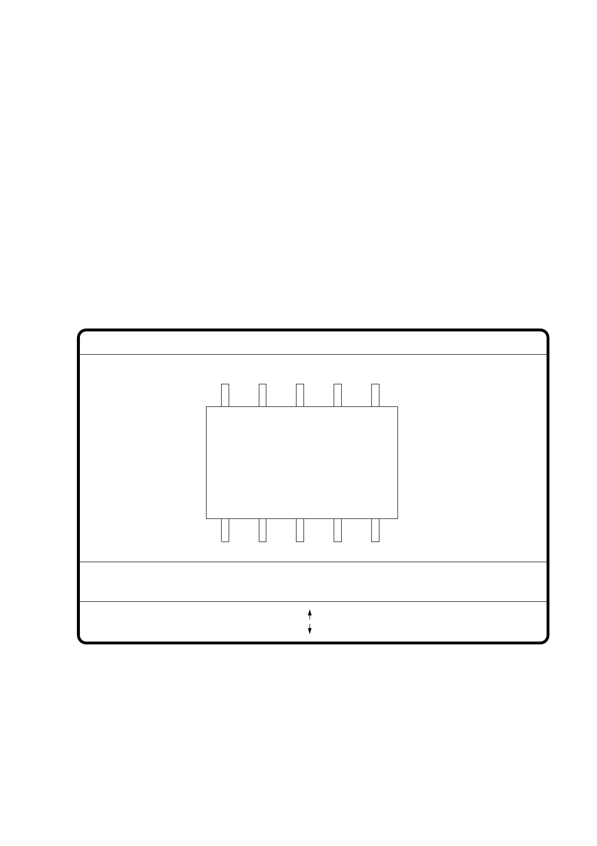
7.6.4.1 Option “Pin dimension”
With this option you can change the optical pin width and length. In addition the pin contrast can also be
changed should the imaging reduction mean that the pins cannot be easily recognized.
Fig. 7.6.18
●
With the Tab key you can select the pin model.
●
With the space bar you can select the pin side.
●
With > and < you raise or lower the pin contrast.
●
With the arrow keys you can change the pin width and length. The component is displayed on the video
screen in its external contours and with the up-dated geometric pin data.
GF No. = 5
Pin dimension
>: contrast +
<: contrast -
opt. l.[mm] = ...
opt. w.[mm] = ...
Pin side =
Pin definition = 1..n
RET: Test component
Tab: Pin model
Blank: Pin side
Pin contrast =
: larger
: smaller
7 Vision Systems SIPLACE 80S/F/G User’s Manual
7.6 Test Component Edition 07/97 from Software Version SR.010.xx
7 - 90 Line engineer
●
With the “RETURN” key you can initiate the individual measurement steps, which form part of the mea-
surement conditions for the specified component.
●
With “ESC” you can abort the option, even if not all measurement steps have yet been executed. You are
returned to the menu “Edit GF data”.
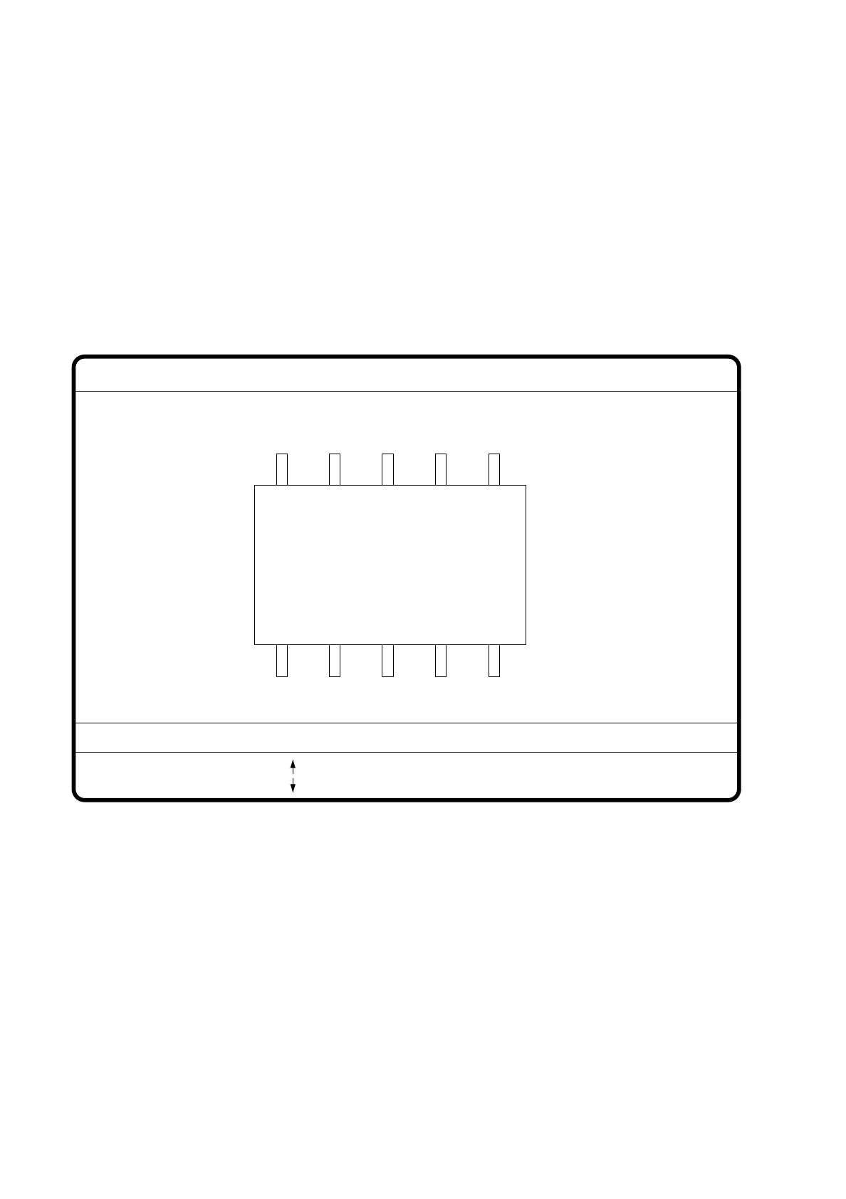
7.6.4.2 Option “Package dimension”
You have the possibility of changing the optical package width and length if the effect of imaging reduction is
excessive. This effect occurs predominantly with cylindrical components.
Fig. 7.6.19
●
With the arrow keys you can change the length and width of the component. The current geometric data
are displayed.
●
With the space bar you can toggle between the sides of the component.
●
With “RETURN” you can initiate the individual measurement steps, which are specified in the measure-
ment conditions.
●
With “ESC” you may quit the option.
GF No. = 5
: larger
: smaller
RET: Test component
Blank: Pack. side
Pack. side = opt. l.[mm] = ... opt. w.[mm] = ...
Pin dimension