00191025-01.pdf - 第406页
SIPLACE 80S/F/G User’s Manual 9 Maintenance Edition 07/97 from S oftware Version SR.010.xx 9.5 Revolver Head, Segment V ersion 2 (New N ozzle Seat) 9 - 47 NOTE The co mponent and PCB visi on systems ( camera, len s and a…

9 Maintenance SIPLACE 80S/F/G User’s Manual
9.5 Revolver Head, Segment Version 2 (New Nozzle Seat) Edition 07/97 from Software Version SR.010.xx
9 - 46
NOTE
The required compensation values for testers 1 and 2 are identical.
The tolerance of the identity tester in the machine, including the entire set-up together with the testing jaws,
amounts to 5 % in each test range.
●
If, despite properly performed C, R, and L compensation, components are still rejected during placement
with identity errors, then to location the fault first check the components with known values and compare
the SETPOINT with the ACTUAL values. If they differ it may be the cause that there is a fault in the identity
tester. This fault can only be corrected by the SMD service department of Siemens AG.
9.5.3 Removal and Reinstallation of the Housing Complete with Star
9.5.3.1 Removal of the Housing Complete with Star
NOTE
Be aware that after reinstallation of the "Housing complete with star" assembly you will require the SIPLACE
test program for the "concluding work".
In the following maintenance work do not apply any grease or oil to the jaws of the centering station.
Do not hold the centering station by the jaws or jaw levers.
●
Remove all segments, as described in the section 9.5.10 Segments, Version 2.
DANGER
∆
!
∆
!
∆
!
Switch the automatic placement system off at the main switch and disconnect from the power supply.
●
Switch off the machine at the main switch.
●
Switch off the compressed air at the supply system.
●
Open the sliding safety doors.
Work to be carried out
Function to be selected
at the computer
(Cursor + Return)
Required value
displayed
on the screen
Comment
C compensation Compensate C < 5.0 pF
Without calibration unit
for identity tester
R compensation Compensate R < 0.5
Ω
With calibration unit for
identity tester
L compensation Compensate L < 0.1
µ
H
With calibration unit for
identity tester
Tab. 9.5.1 Table for checking the compensation values
SIPLACE 80S/F/G User’s Manual 9 Maintenance
Edition 07/97 from Software Version SR.010.xx 9.5 Revolver Head, Segment Version 2 (New Nozzle Seat)
9 - 47
NOTE
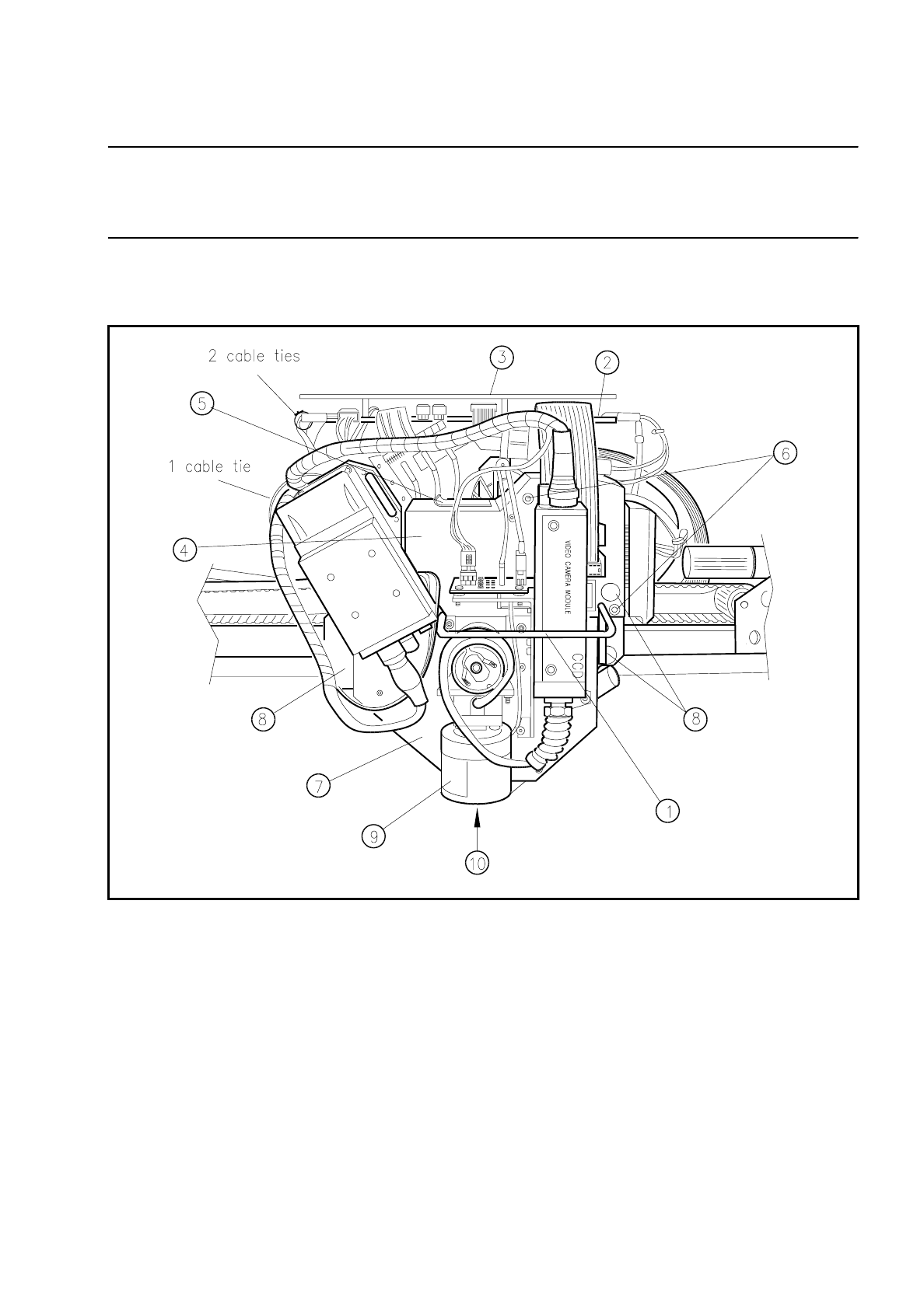
The component and PCB vision systems (camera, lens and amplifier) are not to be removed from the hous-
ing!
●
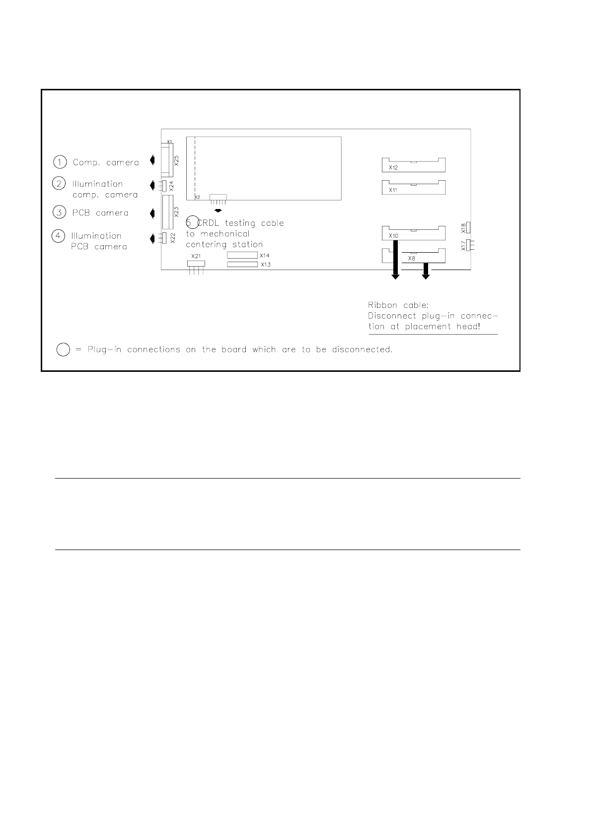
Unplug the plug-in connections of the "conversion board small axis" and of the CRDL test head board
shown in Fig. 9.5.3. The transparent cover over the board need not be removed.
Fig. 9.5.2 Removal of the "Housing complete with star" and location of the PCB camera optical system
Key:
1 Handle 6 Fastening of light gate (2 allen screws M3)
2 Conversion board small axis 7 Housing complete with pulse generator and star
3 Transparent cover 8 Fastening of the “housing compl.” (3 allen screws M4)
4 Light gate 9 Lens of the PCB camera
5 Flap for segment removal 10 Diffusor disk
9 Maintenance SIPLACE 80S/F/G User’s Manual
9.5 Revolver Head, Segment Version 2 (New Nozzle Seat) Edition 07/97 from Software Version SR.010.xx
9 - 48
Fig. 9.5.3 Conversion board small axis and CRDL test head board: disconnecting the plug-in connections
●
Unplug the two plug-in connections of the ribbon cable on the front of the placement heads (see Fig.
9.5.3).
●
Remove the light gate from the placement head: unscrew 2 hexagon socket screws M3 and remove the
cover in an upwards direction.
●
Have the "mounting rack for housing" ready.
CAUTION
∆
!
When removing the housing pay particular attention to the lens of the PCB and component camera! Do
not knock against any part of them!
●
Remove the "housing complete with star" (= without segments) from the "support plate complete":
●
Unscrew the 3 hexagon socket screws M4 (see Fig. 9.5.2) and carefully lift the housing using both
hands off the centering pins of the support plate.
●
Place the housing with its locating holes (the star points upwards!) onto the centering pins of the "housing
mounting rack".
●
Now carry out the maintenance work on the star, screwdrivers 1 and 2, on the mechanical centering station
and on the turning stations dp1 and dp2.