00191025-01.pdf - 第311页
SIPLACE 80S/F/G User’s Manual 7 Vision Systems Edition 07/97 from S oftware Version SR.010.xx 7.9 Test Co mponent: Additions to the 80F M achine Line engi neer 7 - 119 7.9.2 Menu “Edit GF data” 7.9.2.1 O ption “Adjust co…
7 Vision Systems SIPLACE 80S/F/G User’s Manual
7.9 Test Component: Additions to the 80F Machine Edition 07/97 from Software Version SR.010.xx
7 - 118 Line engineer
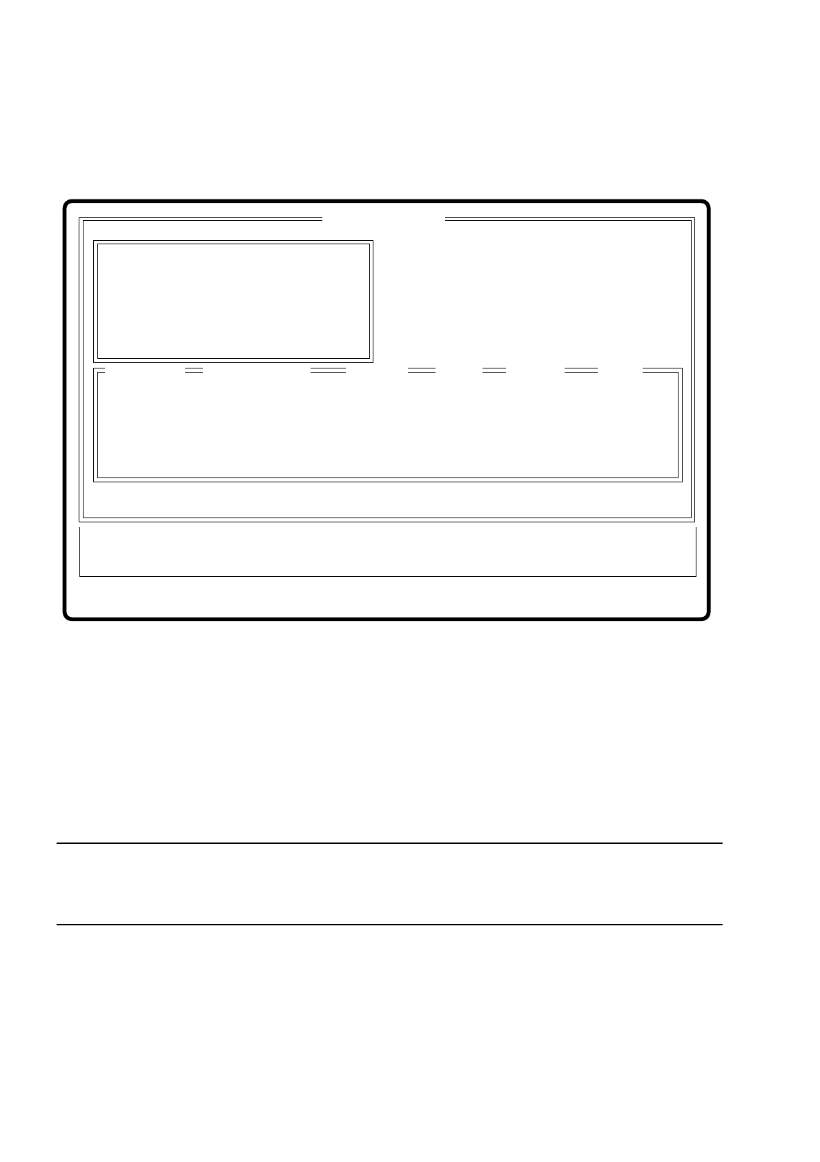
7.9.1 Dialog box “Enter GF number”
After selecting the option “Enter GF number” the dialog box “Enter GF number” pops up.
Fig. 7.9.2
If you have already changed measurement conditions or GF data, you are asked whether you want to discard
or save the data. This is described under Section 7.6.3.1 Option “Enter GF number”.
The only difference between the dialogue box which drops down after this question and the same box with the
80S (Section 7.6.3.1) is that the 80S machine is equipped with one component vision system at each of the
two revolver placement heads, while the 80F machine has one component vision system at the revolver head
and that up to two component vision systems installed in the machine base can be used for the IC placement
head. The component vision system with IC sensor centers fine-pitch components and BGAs, while the com-
ponent vision system with FC sensor centers flip chips and fine-pitch components.
NOTE
Select the option boxes SP head, IC head or IC head FC sensor only when you intend to insert components of
the same type with both the SP head as well as the IC head.
●
With the Tab key you can jump between input, list and option boxes.
●
With the arrow keys you can select the item in the individual boxes.
●
With the space bar you can mark a component in the list box or the vision system in the option box.
●
With “RETURN” the data are transferred to the program and the dialog box closed. You are returned to the
menu “Test component”.
●
With “ESC” you can abort the dialog without saving and return to the menu “Test component”.
Enter GF number
Esc: abort Ret: input
GF number
:
Component name
:
Location
:
Track
:
Division
Level
:
:
Blank: select
Enter GF number
GF number
Component name
Track
Division
Level
Tab: change wind.
Input box
Options box
List box
Location
Error
State
Action
:
:
:
Vision system
( ) SP head
( ) IC head
( ) IC head FC sensor
X
SIPLACE 80S/F/G User’s Manual 7 Vision Systems
Edition 07/97 from Software Version SR.010.xx 7.9 Test Component: Additions to the 80F Machine
Line engineer 7 - 119
7.9.2 Menu “Edit GF data”
7.9.2.1 Option “Adjust component type”
With the 80F machine the Menu “Edit GF data” (description see Section 7.6.4) was expanded by the addition
of the option “Adjust component type”.
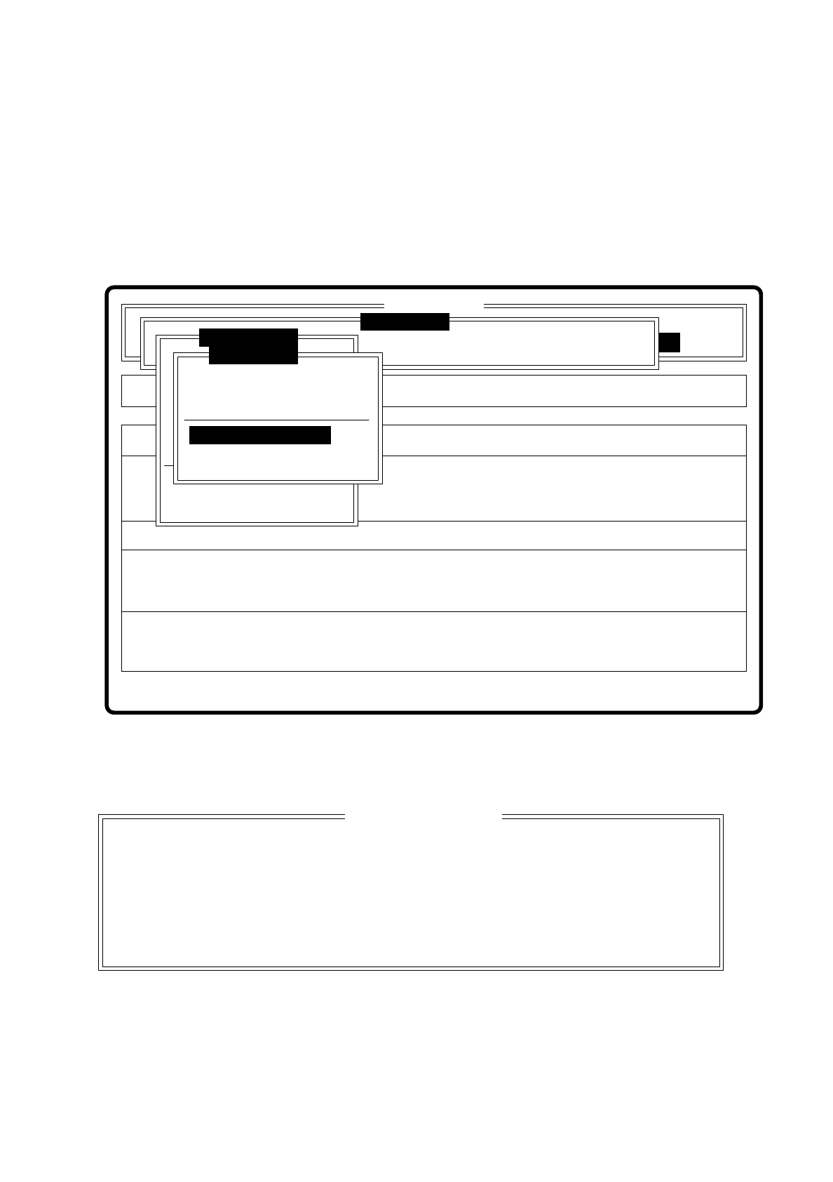
Fig. 7.9.3
When you select this option the following option box pops up.
Fig. 7.9.4
Select this option when centering errors occur with standard illumination. With these 4 selection possibilities
you can achieve optimal adjustment of the illumination to the component in question. Each of these options
contains specific combinations of the types of illumination: shallow, middle and steep angles.
Rüstung:
Single functions
Cluster:
SI80F V 10.x
Vision system
Vision system
Allestimento:
Version: 2133
BE abholen
BE darstellen
BE prüfen
GF-Daten ändern
Mess-Mode ändern
Nachfüllen
Display errors
BE messen
Test component
Edit GF data
Test output
Error
State
Action
:
:
:
Vision system
Select component type
Pin dimension
Package dimension
Ball image
Select component type
Illumination
Program transform
Esc: abort Ret: input Blank: select
Select component type
( ) Cubic, dull white
( ) Cubic, dull black
( ) Cubic, bright
( ) Cylindrical

7 Vision Systems SIPLACE 80S/F/G User’s Manual
7.9 Test Component: Additions to the 80F Machine Edition 07/97 from Software Version SR.010.xx
7 - 120 Line engineer
Key functions
●
With the space bar you can mark the corresponding component type
●
With “RETURN” finish making entries, and the option box is closed. You are returned to the menu “Edit GF
data”.
●
With “ESC” you may quit the option box, without accepting any change which may have been made.
7.9.2.2 Option “Illumination”
The option illumination has already been described for the revolver placement head in Section 7.6.4.4. You
have the possibility of choosing between two planes of illumination, shallow and steep.
For the component vision system of the IC head this option provides three planes of illumination:
–
shallow (bottom LED level)
–
middle (middle LED level)
–
steep (top LED level)
The keyboard commands are the same as those described in Section 7.6.4.4.