00191025-01.pdf - 第576页
SIPLACE 80S/F/G User’s Manual 17 Nozzle Surve y Edition 07/97 from S oftware Version SR.010.xx 17.1 Nozzle Contour Diagrams 17 - 7 Fig. 17.1.5 Corr elation between components height difference and placem ent shadow - Key…
17 Nozzle Survey SIPLACE 80S/F/G User’s Manual
17.1 Nozzle Contour Diagrams Edition 07/97 from Software Version SR.010.xx
17 - 6
17.1.2 Representation of a Nozzle Contour Diagram
You can obtain the following information from a nozzle contour diagram:
-
Placement shadow in [mm]
-
Components height difference in [mm]
NOTE
The placement shadow is defined as the distance required between two components when they are
inserted and taking the height difference into account.
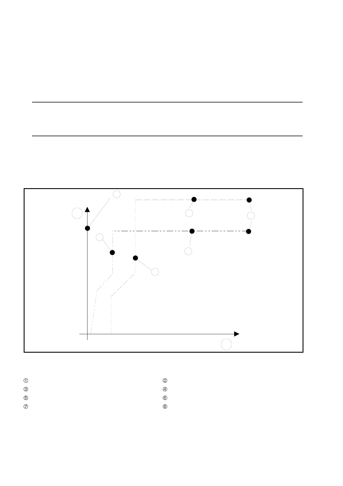
A nozzle contour diagram depicts all of the nozzle contours of a nozzle type.
As an example, Fig. 17.1.4 'Representation of multiple nozzle contour diagrams' shows two nozzle contours in
one diagram.
Fig. 17.1.4 Representation of multiple nozzle contour diagrams
- Key to Fig. 17.1.4
Components height difference in [mm] Placement shadow in [mm]
Center of nozzle Nozzle contour of nozzle B
Nozzle contour of nozzle A Encoder disk of nozzle B
Encoder disk of nozzle A Outside edge of encoder disk
A correlation between the components height difference and the placement shadow can be derived from
these values (see Fig. 17.1.5 'Correlation between components height difference and placement shadow').
4
1
3
7
6
8
5
2
SIPLACE 80S/F/G User’s Manual 17 Nozzle Survey
Edition 07/97 from Software Version SR.010.xx 17.1 Nozzle Contour Diagrams
17 - 7
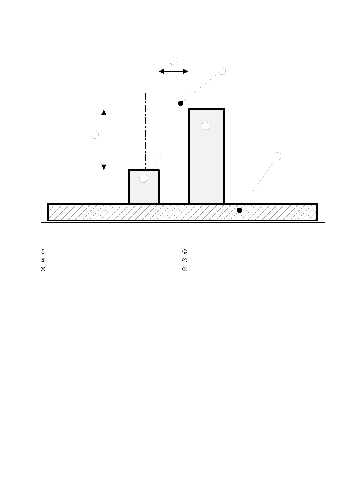
Fig. 17.1.5 Correlation between components height difference and placement shadow
- Key to Fig. 17.1.5
Components height difference Placement shadow
Nozzle contour from diagram PCB
Component 1 Component 2
Component 1 can now be inserted with the selected nozzle as close to component 2 as the height difference
of the two components permits.
1
2
3
4
6
5
17 Nozzle Survey SIPLACE 80S/F/G User’s Manual
17.1 Nozzle Contour Diagrams Edition 07/97 from Software Version SR.010.xx
17 - 8
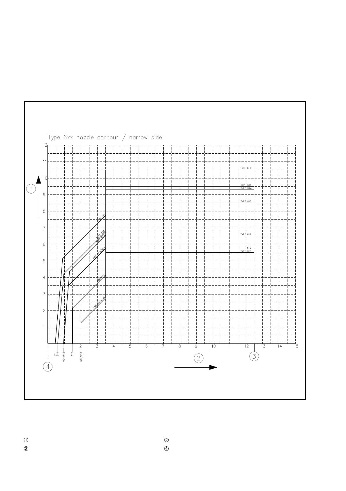
17.1.3 Nozzle Contour Diagrams
Figures 17.1.6 and 17.1.7 show the nozzle contour diagrams for nozzle type 6xx (in each case with the nar-
row and long sides of the nozzle).
Fig. 17.1.6 Nozzle contour for nozzle type 6xx, narrow side
-Key to
Fig. 17.1.6
Components height difference [mm] Placement shadow [mm]
Outer edge of encoder disk Center of nozzle