00191025-01.pdf - 第209页
SIPLACE 80S/F/G User’s Manual 7 Vision Systems Edition 07/97 from S oftware Version SR.010.xx 7.2 PCB Vision System Line engi neer 7 - 17 ● Using existi ng structures as f iduc ials Instead of fiducials y ou can also us …
7 Vision Systems SIPLACE 80S/F/G User’s Manual
7.2 PCB Vision System Edition 07/97 from Software Version SR.010.xx
7 - 16 Line engineer
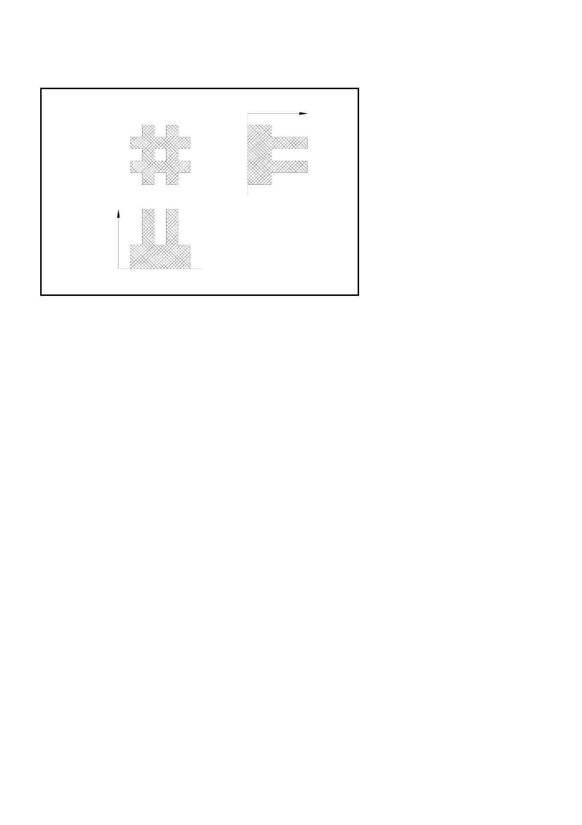
Fig. 7.2.2 Row and column profiles of a double cross
●
The position of the fiducial is precisely determined from the horizontal and vertical profiles. After teaching
is completed the fiducial structure parameters obtained are saved to the line computer.
●
Now the saved definition is tested. The gantry of the PCB camera moves over the board to all 4 corners of
the search area (worst case). In this test the vision system must reidentify the fiducial four times.
●
Finally, the coordinates of each individual fiducial (at least two) are entered manually into the NU-file or
transferred from the CAD file into the NU-file. In this way the coordinates and fiducial structure parameters
for the board which is to be placed are defined in the system as a model.
●
During the placement sequence the fiducial parameters are again determined using the image processing
methods described above (2D and 1D procedures). The pattern search window is moved over the search
area in moxel steps and a search is made for the greatest possible agreement between the grey-scale val-
ues of the reference pattern and the PCB search pattern (correlation procedure). Maximum correlation is
attained where the reference and search patterns agree.
●
When the fiducial has been found, the 1D pattern search procedure starts with a very precise determina-
tion of the geometry and coordinates of the fiducial. The precise fiducial template and coordinates are now
in each case determined via the column and row profiles (see Figure above) by means of the correlation
procedure. Position, rotation and shear of the board are determined using the coordinates obtained.
Reject fiducials (= ink dots) are also recorded and evaluated using the method described above.
7.2.5 Criteria for the creation of fiducials
As a fundamental rule the same criteria shall apply to both fiducials and also to reject fiducials (ink dots): clar-
ity of the fiducial shapes and easily recognizable structures which stand out clearly from their surroundings.
Fiducial
Sum of the
grey-scale
values by
columns:
column profile
Sum of the
grey-scale
values
by rows:
row profile

SIPLACE 80S/F/G User’s Manual 7 Vision Systems
Edition 07/97 from Software Version SR.010.xx 7.2 PCB Vision System
Line engineer 7 - 17
●
Using existing structures as fiducials
Instead of fiducials you can also use clearly identifiable structures within the layout. But note here that the
solder resist is accompanied by a drop in contrast.
●
Location of the fiducials
Position the fiducial where there are as few structures as possible and where it will stand out well from its
surroundings. Measuring outwards from the center of the fiducial the clearance should be at least fiducial
size + 1 mm on each side of the fiducial.
●
Types of fiducial
There are 2 types of fiducial:
–
positive fiducials:
The fiducial extends beyond the material of the PCB base.
–
negative fiducials:
The fiducial is etched into the material of the PCB base.
●
Fiducial shape
Always select a well-structured, distinct figure as fiducial shape which is parallel to the axes.
Recommended fiducial shapes:
Rectangle, square or circle
Characteristics
–
Lower information content (fiducials can easily be mistaken for test dots.)
NOTE
Make sure that there are no similar structures in the search area of the fiducials.
–
Less space required in the layout
–
Very robust in comparison to various tin-plating processes (for example hot tinning).
Recommended fiducial dimensions
–
for square and rectangle:
side length 1.2 mm - 2.2 mm
–
for the circle
diameter 1.2 mm - 2.2 mm
Double cross and single cross
Characteristics of the double cross
–
Higher information content
–
Needs more space in the layout
–
Sensitivity with respect to high tinning (bright copper presents more advantages).
–
If too low a fiducial quality is permitted, the risk exists that four incorrect positions will be recognized.
7 Vision Systems SIPLACE 80S/F/G User’s Manual
7.2 PCB Vision System Edition 07/97 from Software Version SR.010.xx
7 - 18 Line engineer
Characteristics of the single cross
–
Information content somewhat lower than with the double cross
–
Needs less space in the layout than the double cross
–
Less sensitive than the double cross where there is high tinning
Dimensions of the fiducials:
Single and double cross
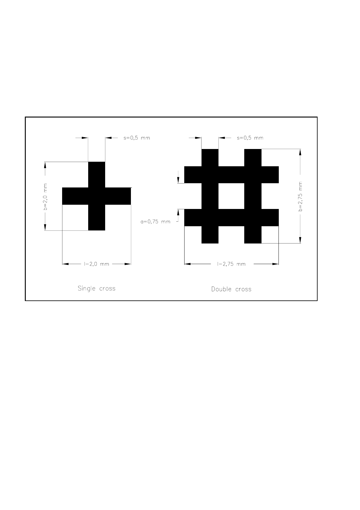
Fig. 7.2.3 Single and double crosses with ideal dimensions
The minimum dimensions for a fiducial as regards length (l) and width (b) will depend on the line thickness
(s) and the structure of the fiducial.
–
length (l) and width (b)
For good recognition of a fiducial the length and the width should be at least 0.9 mm with the single
cross and 1.8 mm with the double cross. The ideal dimensions for the single cross are 2.0 mm and for
the double cross 2.75 mm. Under normal circumstances length and width are equal.
–
line thickness (s)
The line thickness can vary according to standard structure widths and will depend on the type of fidu-
cial. Make sure however that the line thickness is always greater than 0.3 mm. The ideal line thickness
for both fiducial types is 0.5 mm.