00191025-01.pdf - 第430页
SIPLACE 80S/F/G User’s Manual 9 Maintenance Edition 07/97 from S oftware Version SR.010.xx 9.5 Revolver Head, S egment Version 2 (New N ozzle Seat) 9 - 71 Fig. 9.5.16 Maintenance of the eccentric s haft ● Install the sea…

9 Maintenance SIPLACE 80S/F/G User’s Manual
9.5 Revolver Head, Segment Version 2 (New Nozzle Seat) Edition 07/97 from Software Version SR.010.xx
9 - 70
●
Wipe the slide surface dry with a lintfree cloth as specified in the Short Reference Maintenance Segments
Version 2.
●
Continue maintenance with the work described below.
9.5.10.8 Eccentric Shaft: Checking and Replacing the O-Ring,
Cleaning and Maintaining Slide Surface and O-Ring
NOTE
If the eccentric shaft and the hole is not cleaned or maintained, this can lead to stiffness of operation and this
in turn, for example, to the corresponding fatal error message.
Spare part:
O-ring for eccentric shaft, 2 x 1 NBR 55, Item No. 00315630-01, 1 piece
●
Pull the eccentric shaft out of the hole of the segment.
●
Clean and maintain the eccentric shaft with the segment maintenance cloth.
●
Remove any visible particles of dirt.
●
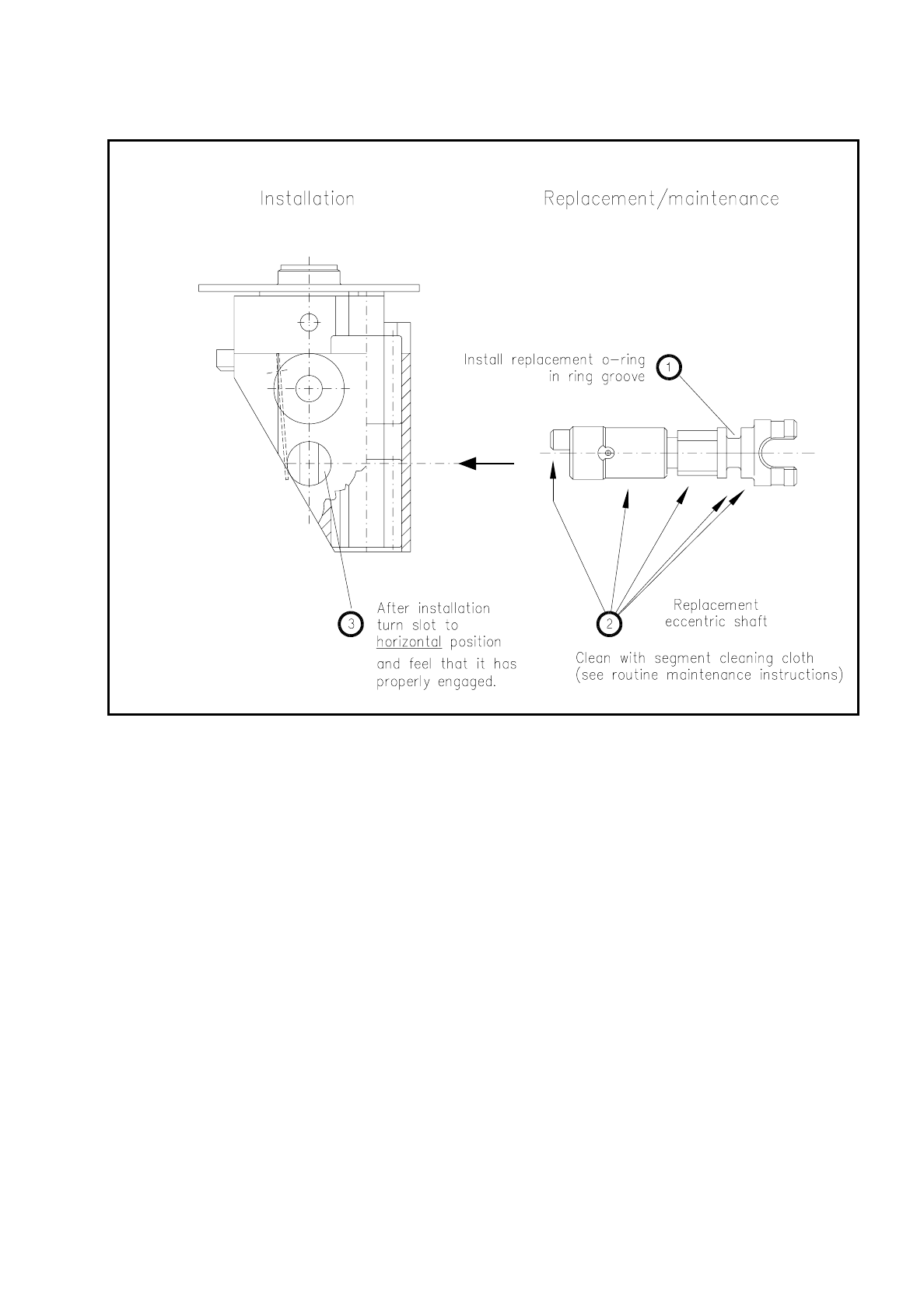
Check the O-ring on the eccentric shaft and if necessary insert a new O-ring in the circumferential groove
of the eccentric shaft (see Fig. 9.5.16).
●
Clean the hole and the ballcatch in accordance with the instructions provided in the Short Reference Main-
tenance Segments Version 2.
●
Remove any fluff deposits thoroughly.
SIPLACE 80S/F/G User’s Manual 9 Maintenance
Edition 07/97 from Software Version SR.010.xx 9.5 Revolver Head, Segment Version 2 (New Nozzle Seat)
9 - 71
Fig. 9.5.16 Maintenance of the eccentric shaft
●
Install the sealing piston as described above.
●
After inspection insert the segments back into the star, as described under "Installation of the segments".
9.5.11 Silencers
9.5.11.1 Checking and Replacing the Silencers
Spare part:
Flow nozzle silencer
, from item no. 00323534S01
9 Maintenance SIPLACE 80S/F/G User’s Manual
9.5 Revolver Head, Segment Version 2 (New Nozzle Seat) Edition 07/97 from Software Version SR.010.xx
9 - 72
CAUTION
∆
!
The maintenance frequency is directly dependent on the quality of the compressed air used (see above "com-
pressed air maintenance unit")!
If the compressed air specification is not complied with, the silencers should be inspected at correspondingly
shorter intervals.
When removing the silencers pay attention to the wiring. Carefully bend it if necessary to one side before-
hand.
Placement head 1 is in the service position.
DANGER
∆
!
∆
!
∆
!
Switch the automatic placement system off at the main switch and disconnect from the power supply.
●
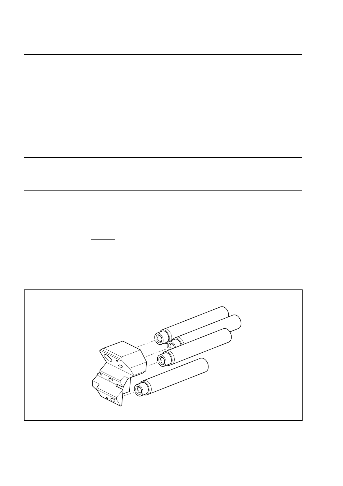
Unscrew and remove - starting at the top - all 4 silencers (see Fig. 9.5.17) in turn from the support plate:
–
Make sure that no parts drop into the machine!
●
Inspect the 4 silencers.
If the silencers are dirty (visible gray - black discoloration), use new silencers.
●
Screw the silencers back into the hole of the support plate in reverse sequence - starting at the bottom -
and as far as the stop.
Attention:
Only use low torque to tighten the silencer since otherwise the silencer
may tear on the thread.
●
Now bring the placement head 2 into the service position: Single functions
→
Gantry 2
→
Go to service
pos'n
→
Start key.
●
Switch off the machine at the main switch and replace the 4 silencers at the placement head 2 (revolver
head, SIPLACE 80 S) analogously to the description for placement head 1.
Fig. 9.5.17 Fitting the silencers