00191025-01.pdf - 第293页
SIPLACE 80S/F/G User’s Manual 7 Vision Systems Edition 07/97 from S oftware Version SR.010.xx 7.7 Guidelines for Describing P ackage Forms Line engi neer 7 - 101 7.7.3 Shapes and po ssible measuring methods for rough (G)…
7 Vision Systems SIPLACE 80S/F/G User’s Manual
7.7 Guidelines for Describing Package Forms Edition 07/97 from Software Version SR.010.xx
7 - 100 Line engineer
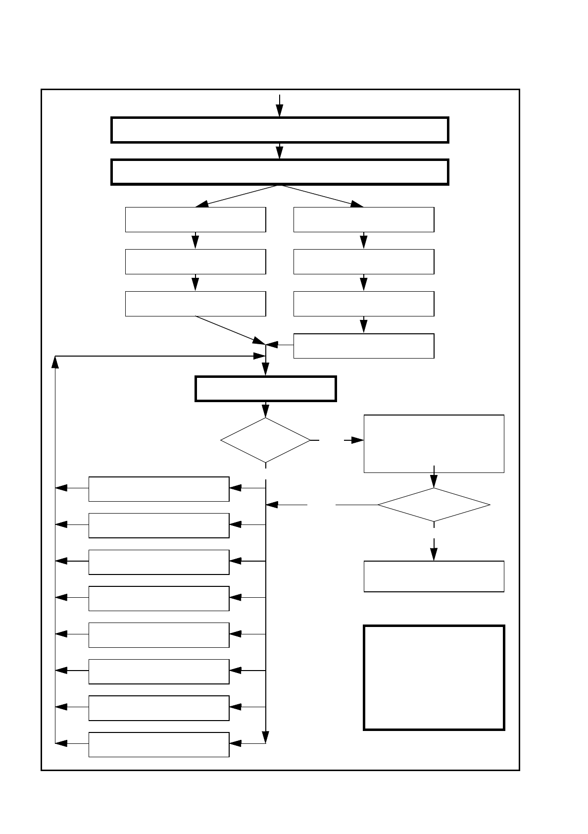
Fig. 7.7.4 Flow chart: ’Programming and testing a package form (GF)’, part 2 - station computer
No
Send program and set-up with this package form to the station and set up
Modify package form as required in "Vision system“ and "Test component“
Revolver head
Pick up GF (component)
IC placement head
Pick up GF (component)
Display component Measure component
Check GF (component)
Return for next measuring step
Display component
Check GF (component)
Return for next measuring step
Measure GF (component)
Error message
occurred?
Yes
Repeat meas. process several
times (move component onto noz-
zle to simulate picking up different
components) and check results
Always identical?
Yes
Assemble component
several times
Important note:
The manipulation of
components at the station
must remain the exception,
rather than the rule.
In general, only a few components
have to be changed.
8. Program contrast
(Program panel)
7. Modify pin/ball
dimensions
6. Modify pin/ball contrast
5. Modify component dimension
4. Modify measuring modes and
measuring
3. Modify lighting
2. Display component
1. Handling error: pick-up angle,
nozzle type, component on nozzle,
No

SIPLACE 80S/F/G User’s Manual 7 Vision Systems
Edition 07/97 from Software Version SR.010.xx 7.7 Guidelines for Describing Package Forms
Line engineer 7 - 101
7.7.3 Shapes and possible measuring methods for rough (G) and fine
centering (F)
*) LEAD with combined evaluation windows for each row of pins replaces the CORNER measuring method.
Measurement of the spacing is replaced by measurement of the (standardized) lead deviation.
If one or more of the results are outside the tolerance,
the component will not be inserted.
If the component cannot be centered correctly, additional measuring methods may be omitted. You should,
however, carry out all the rough centering steps since these reduce the size of the measuring window.
–
In the ’Test component’ menu, the components are optically centered in the individual measuring steps, via
the ’Check component’ function, but the results are not output.
–
In the ’Test component’ menu, the components are optically centered in the individual measuring steps, via
the ’Measure component’ function, but the results are not output.
Design
SIZE
ROW
CORNER
Lead *)
Combined
Lead Separate
Evaluation window
Grid
Ball
Result of the last measuring step
PDC without lead G/F
∆
X,
∆
Y, (
∆φ
), Component length
width, (quality)
PDC rounded image G/F
Angular tolerance
Small FDCs, e.g.
2 leads
G/F
∆
X,
∆
Y, (
∆φ
), Component length
width, (quality)
FDC, regular with short
rows of PINs
G F (F)
Max. deviation from the spacing:
∆
X,
∆
Y,
∆φ,
(quality)
FDC, regular with long
rows of PINs
G F (F)
Max. deviation from the spacing:
∆
X,
∆
Y, (
∆φ
),
quality
FDC
ir
regular with short
rows of PINs
G(G)F(F)
∆
X,
∆
Y, number of PINs (quality)
max. deviation from the spacing
FDC, irregular with long
rows of PINs
G(G)F(F)
∆
X,
∆
Y, number of PINs (quality)
max. deviation from the spacing
FDC, irregular with one
row of PINs, several
PIN models or spacings
GGF
∆
X,
∆
Y, (
∆φ
), standardized lead devia-
tion (quality)
Number of PINs, secondary offset
FDCs with circular seg-
ment PIN arrangements
(G) G F
∆
X,
∆
Y, (
∆φ
), standardized lead devia-
tion (quality)
Number of PINs, secondary offset
BGA, flip-chip G G F
∆
X,
∆
Y, (
∆φ
), spacing,
angle,
quality)
Tab. 7.7.1 Component measuring methods
7 Vision Systems SIPLACE 80S/F/G User’s Manual
7.7 Guidelines for Describing Package Forms Edition 07/97 from Software Version SR.010.xx
7 - 102 Line engineer
–
If the components are larger than 32 mm x 32 mm, a multiple measurement will be carried out automati-
cally in the vision system.
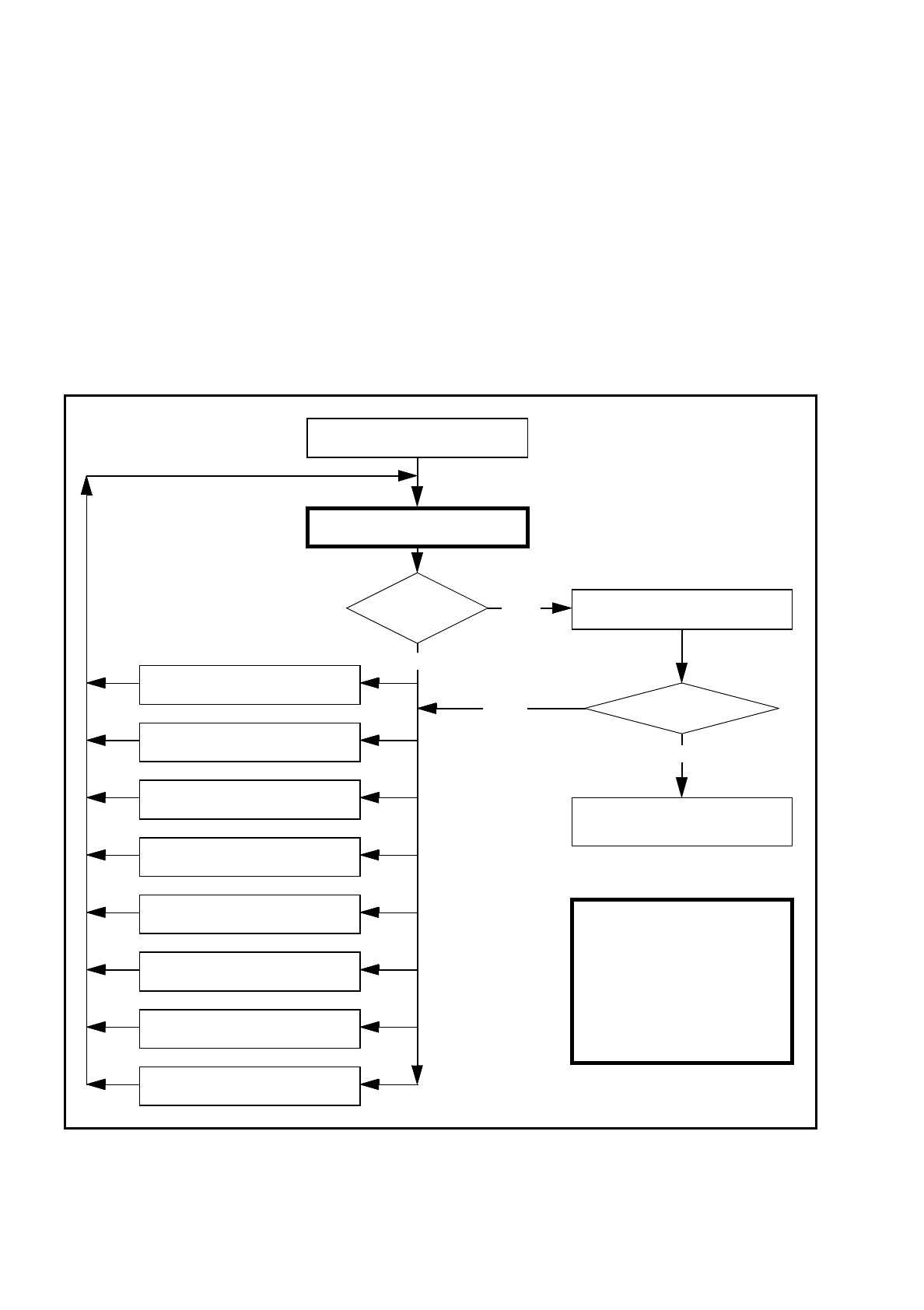
7.7.4 Test Package Form - Visual Representation / Programming Mea-
surement Types
–
In the ’Test component’ menu, a component is picked up and then moved to the camera and mapped in its
0° position. The component is displayed with respect to its insertion angle at the revolver head of the S-15/
F3.
Fig. 7.7.5
Order in which package forms are programmed at the station
Important note:
The manipulation of
components at the station
must remain the exception,
rather than the rule.
In general, only a few components
have to be changed.
Are the results
constant?
No
Measure component
Error
Yes
Repeat the measurement
and view the results
Yes
Assemble component
several times
8. Modify the contrast sensitivity
(Program table)
7. Modify pin/ball
dimensions
6. Modify pin/ball contrast
5. Modify component dimension
4. Modify measuring modes and
measuring
3. Modify lighting
2. Display component
1. Handling error:pick-up angle,
nozzle type, component on nozzle,
No
Measure component
„RETURN“ next measurement