00191025-01.pdf - 第455页
9 Maintenance SIPLACE 80S /F/G User’s Manual 9.8 Camera Systems and Coplanarity Laser Module Ed ition 07/97 from Software Version SR.010.xx 9 - 96 ● Place t he illum ination h ead back vertical ly on th e compon ent came…

SIPLACE 80S/F/G User’s Manual 9 Maintenance
Edition 07/97 from Software Version SR.010.xx 9.8 Camera Systems and Coplanarity Laser Module
9 - 95
9.8 Camera Systems and Coplanarity Laser Module
9.8.1 PCB Camera System in the SIPLACE 80S, 80F and G
The optical system of the PCB camera system requires no cleaning whatsoever.
9.8.2 Component Camera System at the Revolver Head (SIPLACE 80S
and 80F)
The optical system of the component camera system requires no cleaning whatsoever.
9.8.3 Component Camera Systems for the IC Head (SIPLACE 80F)
The locations of the IC head camera system or FC camera system in the machine base is shown in Fig. 9.8.2.
NOTE
Maintenance work for both camera systems is identical.
9.8.3.1 Cleaning Reflecting Surfaces
●
Switch off the machine before removing the illumination head.
●
Pull the illumination head of the component camera with care vertically upwards and off.
●
Cover the now exposed component camera with a box.
●
Wipe the reflecting interior of the illumination head indicated in Fig. 9.8.1 carefully with an absolutely soft,
dry, lint-free and clean cloth. Use special lens cloth (for example from Kodak) or lens cleaning tissue (also
from Kodak).
9.8.3.2 Cleaning the Glass Disk
Remove the glass disk for cleaning as follows:
●
The illumination head will already have been removed from the component camera (see 9.8.3.1).
●
Unscrew and remove the M2.5 hexagon socket screws from the glass holder. Pull the glass holder and the
glass disk with care diagonally downwards and out (see Fig. 9.8.1, Page 9 - 96).
●
Clean the glass disk with a clean and dry lens cloth (see above) or lens cleaning tissue.
●
Fit the glass disk back in the reverse sequence and fasten the glass holder.
9 Maintenance SIPLACE 80S/F/G User’s Manual
9.8 Camera Systems and Coplanarity Laser Module Edition 07/97 from Software Version SR.010.xx
9 - 96
●
Place the illumination head back vertically on the component camera so that the fastening of the glass disk
points to the board conveyor. Make sure the illumination head has been pushed on as far as the stop.
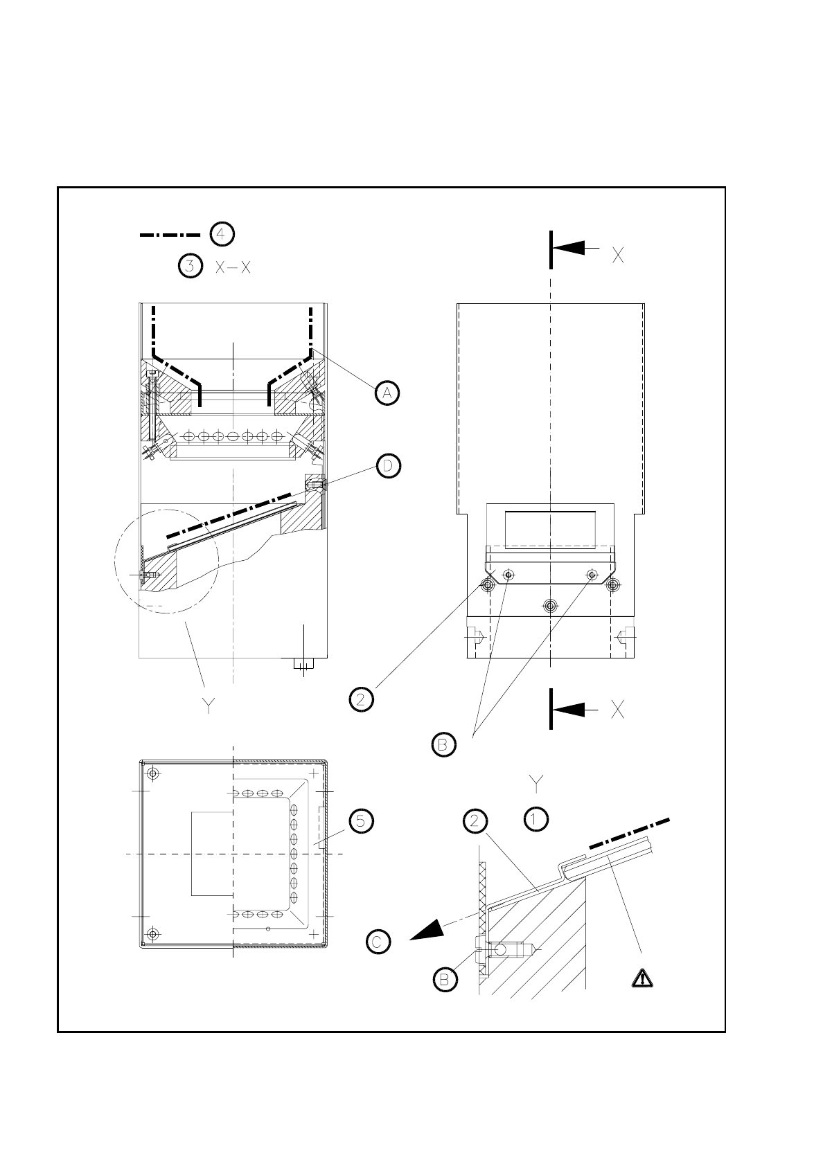
Fig. 9.8.1 Cleaning the illumination head of the IC or FC camera

SIPLACE 80S/F/G User’s Manual 9 Maintenance
Edition 07/97 from Software Version SR.010.xx 9.8 Camera Systems and Coplanarity Laser Module
9 - 97
Key to
Fig. 9.8.1
1 Detail Y 3 Section X-X
2 Glass holder 4 Surfaces to be cleaned
∆
!
glass plate
5 Viewing IC illumination head
Sequence of work in
Fig. 9.8.1
A Clean these surfaces on all sides (applies to IC camera only) and only if the glass disk is dirty.
B Unscrew and remove the hexagon socket screws.
C Pull the glass holder diagonally downwards and away.
D Clean this area.
9.8.4 Coplanarity Laser Module (SIPLACE 80F)
9.8.4.1 Safety Instructions
DANGER
∆
!
∆
!
∆
!
The coplanarity laser module when without safety
devices corresponds to laser class 3B: the laser
works in a wavelength and power range which is
dangerous for eyes and skin.
Only when the safety features have not been mod-
ified does the module correspond to laser class 1
and can be operated without endangering others.
For this reason do not modify or tamper with the
safety devices.
NOTE
Safety devices for operating the laser module in laser class 1:
The safety plug in the laser module will prevent the laser being operated outside the machine.
When one of the safety hoods is opened the operating voltage will be interrupted and the operating voltage
LED will go out at the laser module.
This safety feature will remain in force even when the key-operated switch has been operated (unlocked).
DANGER
∆
!
∆
!
∆
!
Switch off the automatic placement machine at the main switch and disconnect from the power supply before
carrying out maintenance work.
K
INVISIBLE LASER RADIATION
DO NOT EXPOSE TO BEAM
LASER CLASS 3 B
2.4 MW MAX., 750 NM;
AS PER IEC 825-1(1993)
K