SG_FSE_SiplaceHF_HF3_00193901-05_eng.pdf - 第100页
1 - 30 S tudent Guide SIPLACE HF/HF3 3 Communication and Control Edition 09/2005 30 I/O Modul SUB Distributor: (Input s) 3 nc= not connec ted (Reserv e) Connector s I / O Descripti on / Note X3_1 Di0 M_E-Stop Loop1ok or …
1 - 29
Student Guide SIPLACE HF/HF3
Edition 09/2005 3 Communication and Control
29
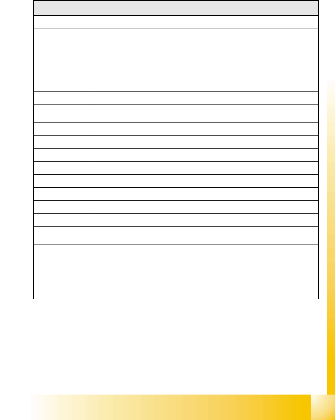
I/O Modul Main Distributor: (Outputs) 3
3
Connectors I / O Description / Note
X7_1 Do0
nc
X7_2 Do1
Ctrl_ON or Software release Only if on Port a "high"-Signal (24V) permanently, then you
can start the machine. The message M_Ready changed from "low" to "high" (EA1/
Di9),if Relay K5 latched. These contacts switch the power supply 24V, the safety loop
1and the Start-buttons on the SSK(K6). When all 6 covers closed, all 4 Feeder flaps,
the two E-Stop buttons and all COT‘s connected, can you press the Start-button and
the SSK is latched. The SSK operate:1.dthe relay K2, K3 and K4 ON and with the
time delay the intermediate circuit voltage for the X-, Y- und Star-Servo boards. 2.the
power supply 24V, 3. the pressure air (Valve) for the tape cutter.4.the two safety loops
for the MTC‘s 5.the power supply for the conveyor motors ON.
X7_3 Do2
Ctrl_pressure air (Reserved)
X7_4 Do3
St_pressure air C&P/Twinpressure OFF (If ON "low" Signal opened the pressure main
valve. A "high" Signal closed this.
3
X7_5 Do4 St_Component Counter / each "high" -Impuls added the counter to one.
X7_6 Do5
nc
X7_7 Do6
nc
X7_8 Do7
nc
X8_1 Do8
nc
X8_2 Do9
nc
X8_3 Do10
nc
X8_4 Do11
nc
X8_5 Do12
St_green light 1 / The right green light of the fault indicator lamp flashed if an
"high" signal on
the port output. Definition: Flashed when no PCB board in the right conveyor lane.
X8_6 Do13
St_white light 1 / The right white light of the fault indicator lamp flashed if an "high"
signal on the port output. Definition: Fault on a feeder on location 1 or 2.
X8_7 Do14
St_white light 2/ The left white light of the fault indicator lamp flashed if an
"high" signal on
the port output. Definition: Fault on a feeder on location 3 or 4.
X8_8 Do15
St_green light 2/ The left white light of the fault indicator lamp flashed if an
"high" signal on
the port output. Definition: Flashed when no PCB board in the left conveyor lane.
1 - 30
Student Guide SIPLACE HF/HF3
3 Communication and Control Edition 09/2005
30
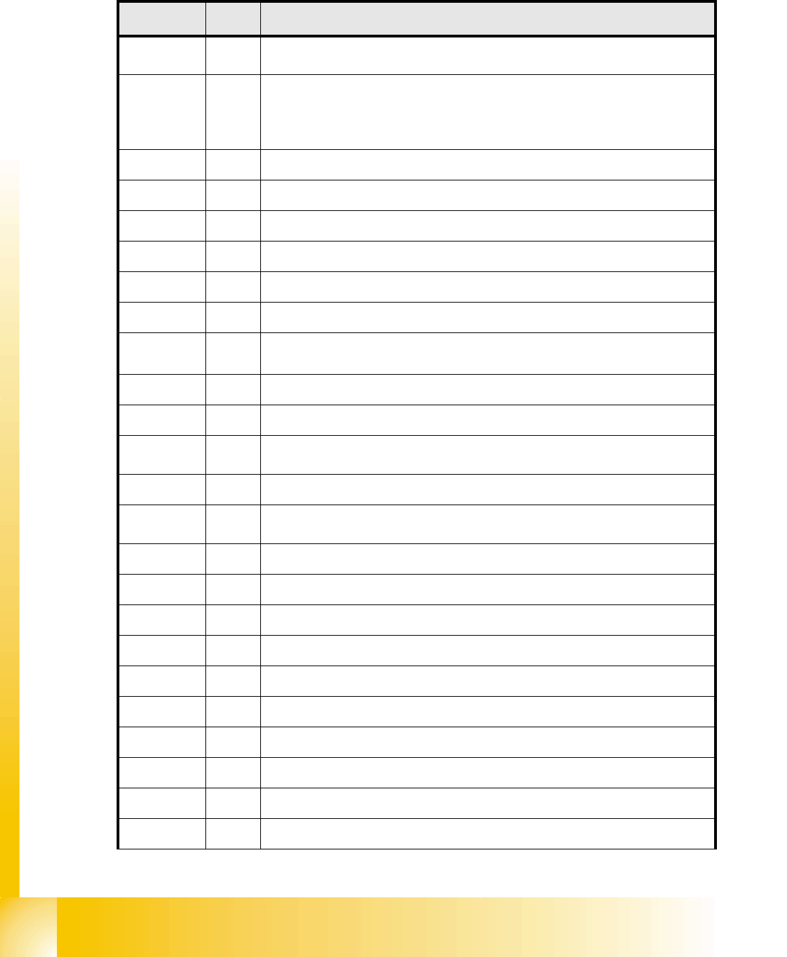
I/O Modul SUB Distributor: (Inputs) 3
nc= not connected (Reserve)
Connectors I / O Description / Note
X3_1 Di0
M_E-Stop Loop1ok or M_Security Loop("high" signal if all safety loops closed
(Covers, E-Stop Buttons, Feeder flaps, COT‘s).
X3_2 Di1
M_D0ServoAddress Bus Bit-0 from the Servoaddress!
Each servo card get a number (0-16) for the Identification. This number can be reconstruc-
ted from all 4 servo address bus messages. In the interaction with the outputs EA2/Do0 to
EA2/Do4 every servo board can be checked in the provided slot.
X3_3 Di2
M_D1ServoAddressBus Bit-1 from the Servoaddress!
X3_4 Di3
M_D2ServoAddressBus Bit-2 from the Servoaddress!
X3_5 Di4
M_D3ServoAddressBus Bit from the Servoaddress!
X3_6 Di5
M_Pressure sensor main valve / "high" Signal when pressure level reached
X3_7 Di6
nc
X3_8 Di7
nc
X4_1 Di8
M_Start Button
"high" while the start button is pressed. This function activate the safety
combination, all axes are ready.
X4_2 Di9
M_Stop Button "high" Signal while the stop button is pressed.
X4_3 Di10
M_reject box
X4_4 Di11
M_Gantry Crash 2 "low" Signal gantry 1 and 4 if the distance to small, "high" Signal
normal operating status
X4_5 Di12
nc
X4_6 Di13
M_ServoEnable1 or Control ON / "high" Signal - intermediate circuit voltage for X/Y
Servo on Axis Unit 2 goes through.(K4 message)
X4_7 Di14
nc
X4_8 Di15
M_Emergency stop button MTC / "high" Signal emergence stop button activate
X5_1 Di16
X5_2 Di17
M_Cover 1 "high" Signal if cover 1 closed
X5_3 Di18
M_COT 1 "high" Signal if COT 1 connected
X5_4 Di19
M_Cover PCB Input "high" Signal if cover closed.
X5_5 Di20
M_E-Stop button PCB Input "high" Signal if E-Stop not activated.
X5_6 Di21
M_Cover 4 "high" Signal if cover 4 closed.
X5_7 Di22
M_COT 4 "high" Signal if COT 4 connected
X5_8 Di23
nc
1 - 31
Student Guide SIPLACE HF/HF3
Edition 09/2005 3 Communication and Control
31
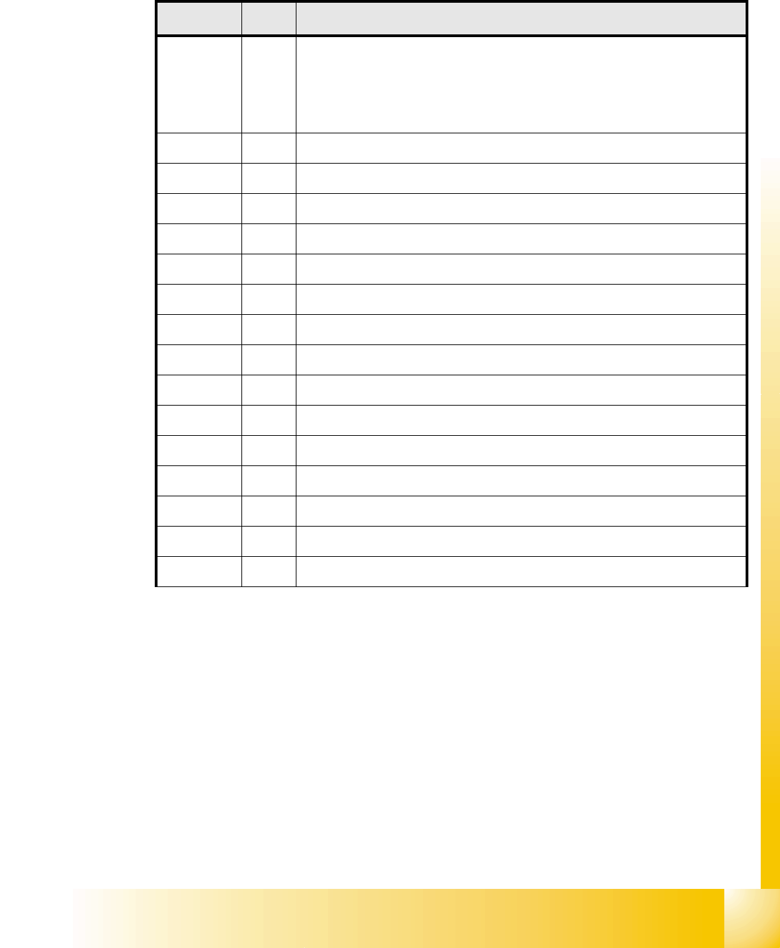
I/O Modul SUB Distributor: (Outputs) 3
nc= not connected (Reserve)
Connectors I / O Description / Note
X7_1 Do0
St_D0ServoSlot Bit-0 of the servo slot identification
Each servo card get a number (0-16) for the Identification. This number can be
reconstructed from all 4 servo address bus messages. In the interaction with the
outputs EA2/Do0 to EA2/Do4 every servo board can be checked in the provided
slot.
X7_2 Do1
St_D1ServoSlot / Bit-1 of the ServoSlot-Identification!
X7_3 Do2
St_D2ServoSlot / Bit-2 of the ServoSlot-Identification!
X7_4 Do3
St_D3ServoSlot / Bit-3 of the ServoSlot-Identification!
X7_5 Do4
St_D4ServoSlot / Bit-4 of the ServoSlot-Identification!
X7_6 Do5
St_pressure air main valve / ON
"low" Signal open the valve
X7_7 Do6
nc
X7_8 Do7
nc
X8_1 Do8
nc
X8_2 Do9
nc
X8_3 Do10
nc
X8_4 Do11
nc
X8_5 Do12
X8_6 Do13
X8_7 Do14
X8_8 Do15