SG_FSE_SiplaceHF_HF3_00193901-05_eng.pdf - 第287页
1 - 87 S tudent Guide SIPLACE HF/HF3 Edition 09/2005 6 Colle ct &Place-Head / DLM2 87 12 segment C&P head DLM2 - signal for S t ar axis 6 Fig. 6.6 - 8 Dynamic signals St ar-Axis 12segment C&P head DLM2 6 segm…
1 - 86
Student Guide SIPLACE HF/HF3
6 Collect &Place-Head / DLM2 Edition 09/2005
86
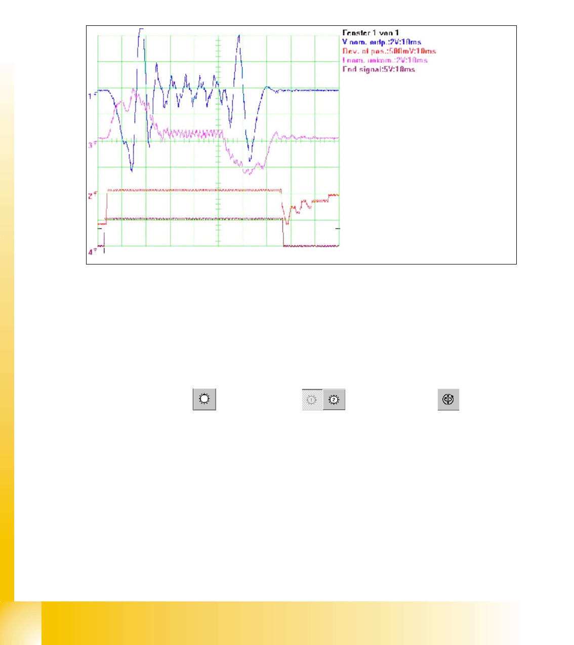
6.6.3.4 Example for dynamic with the control signal of the Vnom. output
The Axis dynamic of the Star axis is checked with Star step continuos run. At Vnominal output of
the Axis tester pass a motor current signal. (Control signal1) The uncommutated nominal current
signal (Signal 3) show the friction of the axis system it show also increased friction.
The positioning time for the Star axis step is 70 ms (6 segment C&P head) and for the 12 segments
C&P head 46 +/-3 ms.
Fig. 6.6 - 7 Dynamic signals Star axis for excample 6 segment C&P head
Legend
SITEST: 6
➠ Select "C&P heads" ==> "Select head" ==>"Axis functions" ==> "Select
Star-axis" ==> "Continuous run Star" ==> Edit: Waiting time "500 ms" ==> "Accept".
➠ If necessary, press the START button.
(1) Control signal (Axis testbox V
nom.) (2) Uncommutated Current signal Axis adapter
(3) Position of deviation (4) End signal
1
2
3
4
1 - 87
Student Guide SIPLACE HF/HF3
Edition 09/2005 6 Collect &Place-Head / DLM2
87
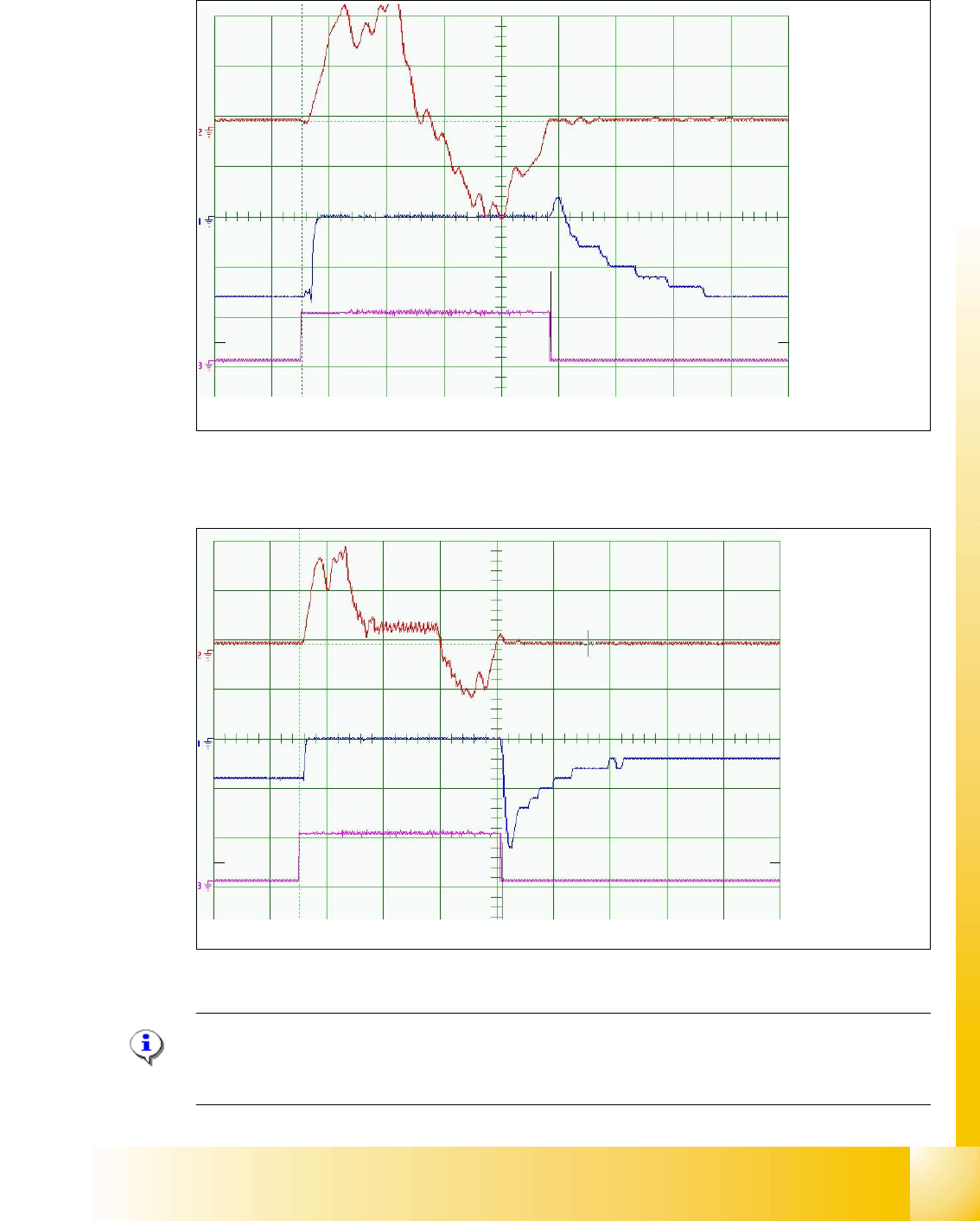
12 segment C&P head DLM2 - signal for Star axis
6
Fig. 6.6 - 8 Dynamic signals Star-Axis 12segment C&P head DLM2
6 segment C&P head DLM2 - signal for Star axis 6
6
Fig. 6.6 - 9 Dynamic signals Star axis 6 segment C&P head DLM2
Please Note:
If the positioning time to slow, please check the friction of the distributor disk and the magnetic
neutral position of the star motor. 6
Current nominal
Deviation of pos.
End signal
10ms/Div
2V/Div
500mV/Div
Positioning time: 46ms +/- 3 ms 1 Star step= 30000 Digits = 30°degree
Positioning time: 70ms +/- 3 ms 1 Star step= 60000 Digits = 60°degree
Current nominal
Deviation of pos.
End signal
10ms/Div
2V/Div
500mV/Div
1 - 88
Student Guide SIPLACE HF/HF3
6 Collect &Place-Head / DLM2 Edition 09/2005
88
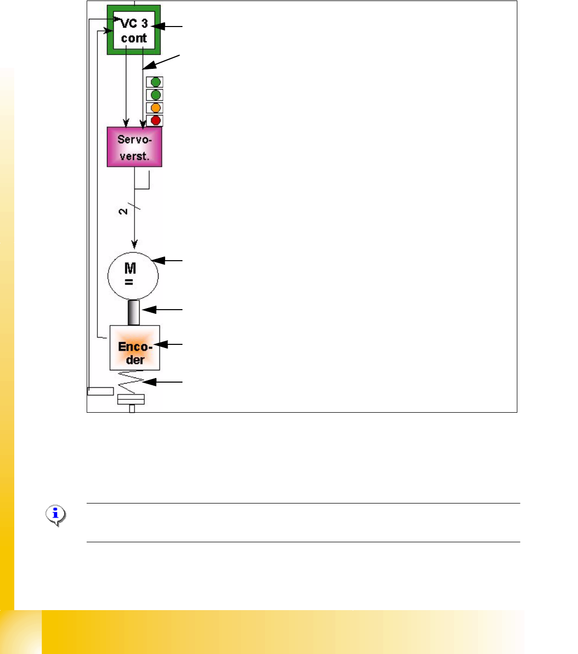
6.6.4 Axis control Z-Axis
The Z-axis is driven with a DC servo motor. The control of the axis occurred with one control si-
gnals of the VC3 controller I
nom "W" and I nom "U" = 0. The intermediate circuit voltages is
approx. 60V.
Fig. 6.6 - 10 Axis control Z-Axis
6.6.4.1 Check the dynamic Z-Axis
6.6.4.2 Test setup
Please Note:
The test setup for the Z-Axis is the same as the Star-Axis
The positioning time for the Z-Axis is 30ms +/-3ms (6 segment C&P head) and 24ms, -1 ms of the
12 segment C&P head.
Axis controller ’A363’ with VC 3 Controller (VC = Velocity Commutation)
Control signal I
nom "W"
LED‘s on the Servo amplifier:
– Power supply ON
– Servo enable, if the the enable signal from the axis board available.
– Display R.M.S. current limiter shorter than 2,5 s.
– Error: Overvoltage, -current, -temperature or Nominal current-over-
stepping longer than 2,5 sec.
Servo board control directly the DC motor.
DC motor.
Between the motor and the incremental encoder exist a fixed mechanical
combination.
Incremental encoder: transmit the exact position of the axis via the track
signals.
Elastic mech. Combination (Belt) and light barrier below, for the fast
recognition of the lower position.