SG_FSE_SiplaceHF_HF3_00193901-05_eng.pdf - 第410页
1 - 24 S tudent Guide SIPLACE HF/HF3 9 Modular convey or Edition 09/2005 24 Fig. 9.2 - 13 Diagrams PCB braking Due to the automatical teachin g of the Slow PCB approach the time to reach the stopper po sition is constant…
1 - 23
Student Guide SIPLACE HF/HF3
Edition 09/2005 9 Modular conveyor
23
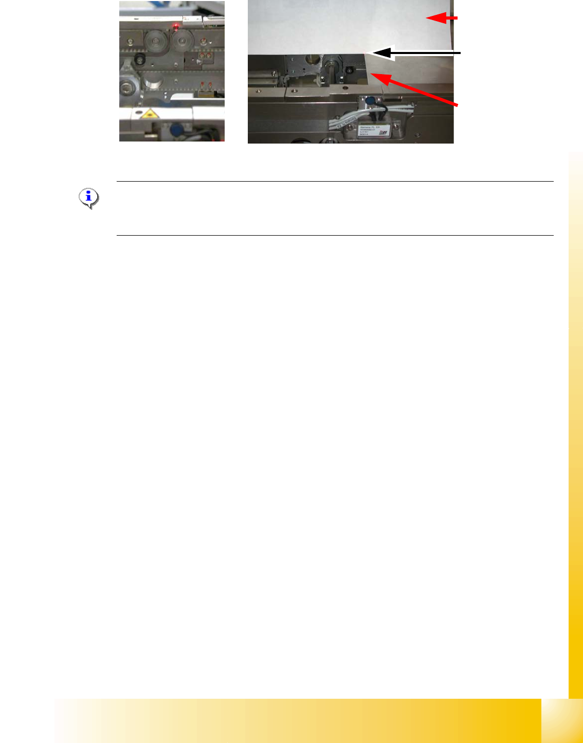
Fig. 9.2 - 12 Focussing the laser beam
Please Note:
When you move the paper, the beam must follow along the edge of the PCB as accurately as pos-
sible, with minimal deflection to the left and right.
9.2.7 Setting the light barrier in the placement area
Function: 9
– Switching on the laser light barrier
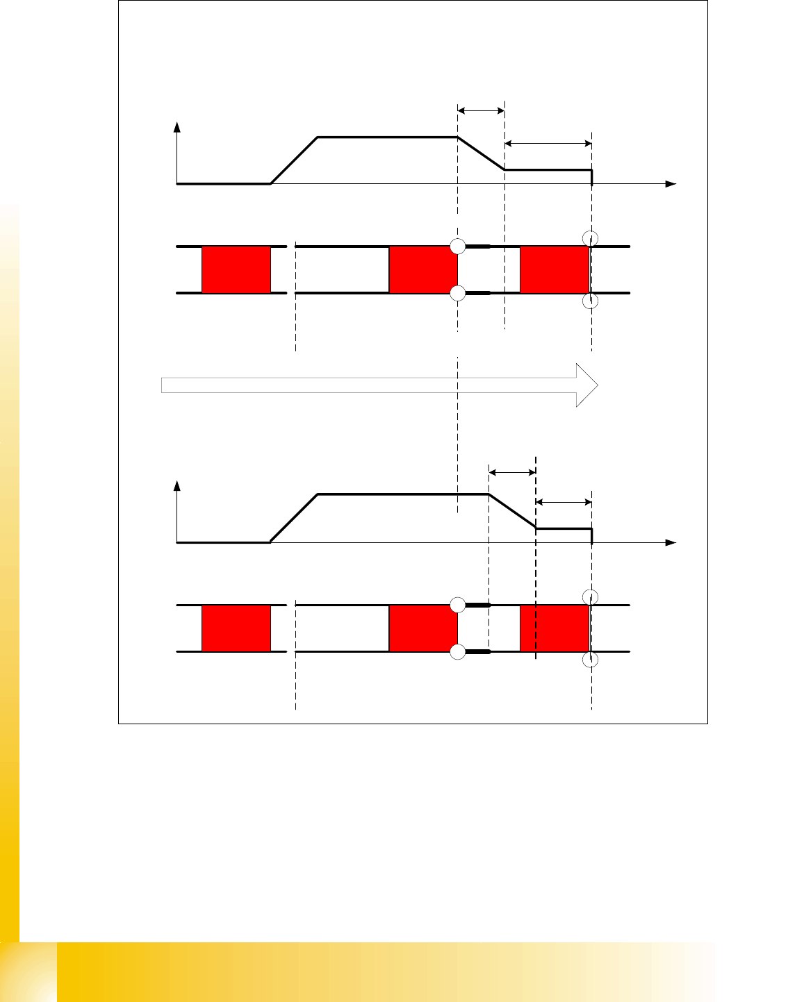
– Starting the PCB braking, see Fig. 9.2 - 13.
The light barrier in the placement area can be mounted in three different positions. The light barrier
is fitted in the direction to the input conveyer. The light barrier then trigger the LASER stopper and
slow down the PCB movement. The
slow PCB approach is teached automatically via soft-
ware.The travel profile for braking the PCB (see Fig. 9.2 - 13) is started in good time to allow the
PCB to be stopped reliably at the laser light barrier after no more than 100 ms.
Paper
PCB with the laser
beam parallel to it
Visible
laser beam
1 - 24
Student Guide SIPLACE HF/HF3
9 Modular conveyor Edition 09/2005
24
Fig. 9.2 - 13 Diagrams PCB braking
Due to the automatical teaching of the Slow PCB approach the time to reach the stopper position
is constant irrespective of the PCB weight. The transport time keeps constant.
Direction of PCB transport
Time (t)
< 100 ms
Light barrier
Laser
Travel profile
braking process
Start End
Placement areaInput belt
2nd board
Time (t)
Speed (v)
150 ms
Laser
Travel profile
braking process
Start End
Input belt
1st board
Speed (v)
Placement area
Light barrier
1 - 25
Student Guide SIPLACE HF/HF3
Edition 09/2005 9 Modular conveyor
25
9.2.8 Setting the light barrier in the input,- intermediate- and output conveyer
Function: 9
– Recognizing and stopping the PCB boards.
– PCB monitoring in the input conveyer, that means
Is a PCB recognized in the input conveyer and this PCB appears on the station GUI, then the
machine closes the interface to the previous station. With PCB boards with outbreaks it can
happen that the PCB, is stoped, however, the signal of the light barrier goes out and the inter-
face to the previous station is opened again. Then the next PCB would move into the input con-
veyer with the PCB still lying in the input conveyer. With PCB monitoring the PCB is moved
backwards and once again forwards, untill the light barrier switches.
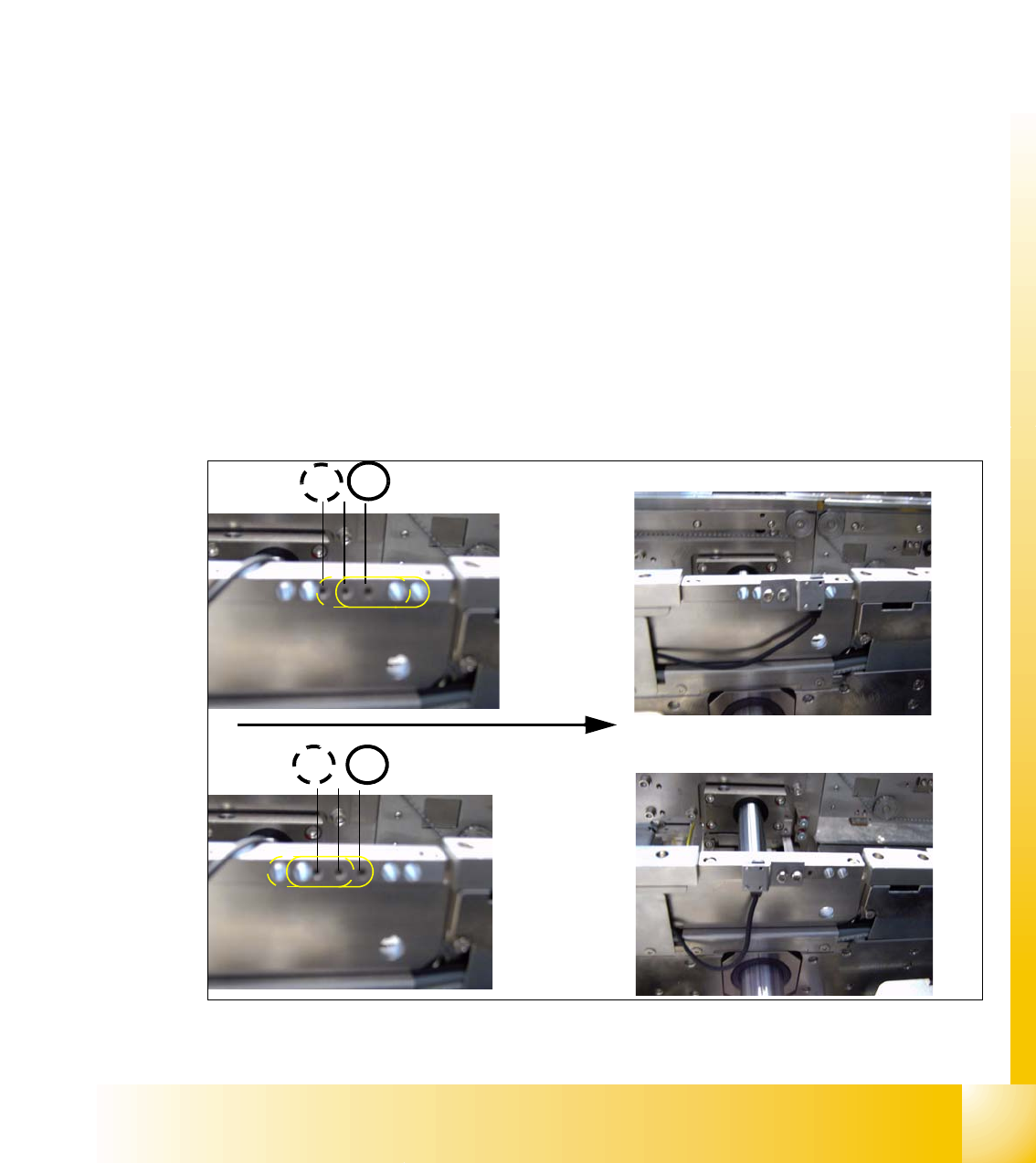
Assembly position for the receivers in the input-,intermediate- and output conveyer 9
The receivers can be assembled in four different positions, this is necessary if you have LP‘s with
outbreaks and for small and wide PCB‘s. For normal PCB boards you can use the standard posi-
tion 3/4 of the receiver. If you have wide PCB‘s it make sense to use the position 1 or 2, because
the stop distance is longer.
– The receivers are fixed with two screws on the conveyer rail.
– Three drillings are in the conveyer rail, so there are two positions for mounting the receiver.
– Another two positions are posibile by turning around the sensor bracket at the receiver. (see
chapt.Fig. 9.2 - 14)
Fig. 9.2 - 14 Assemble position for the light barrier receivers
4
3
Example for Assemble position 3
1 2
Transport direction
Example for Assemble position 1